In-depth analysis of DC-AC converter inverter
Source: InternetPublisher:newlandmark Keywords: Inverter AC voltage DC voltage Updated: 2024/12/10
A device that converts DC voltage to AC voltage is called a DC–AC converter or "inverter". The inverter converts the battery voltage (such as 12V DC or 24V DC) to 110V AC or 220V AC. The power sockets we use in our lives have 220V/110V. We have no way to store AC power, but we can store DC power in batteries. Therefore, in order to save power in household sockets, the development of AC-DC converters (rectifiers) has emerged.
These DC batteries can provide DC current, and our equipment is designed to use AC power. Therefore, the development of inverters came into being.

Full-bridge inverter
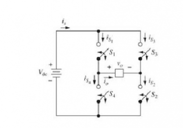
This inverter is constructed using four switches connected in a bridge. By appropriately opening and closing two switches at a time, a 2-level AC (pulsating DC) output can be obtained.
Depending on the state of the switch, the output level will fluctuate between +VDC and –VDC
S1 and S2 are closed, output = +VDC
S3 and S4 closed output = -VDC
S1 and S3 are closed, output = 0
S2 and S4 are closed, output = 0

Real switching requires switching transition time, which is called blanking time.
Square wave inverter
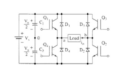
This is the simplest inverter. The supply voltage is Vs. Consider an RL load. When Q1 and Q2 are conducting, the output is connected to +Vs. When Q3 and Q4 are conducting, the output is connected to –Vs. This AC output voltage is not exactly like a sine wave, but has some AC characteristics that can be useful in some applications.
The current flowing through the switch must be bidirectional, but real switches such as insulated gate bipolar transistors (IGBTs) can only flow in one direction. So we add anti-parallel feedback diodes to each switch. During the intervals when the switch current should be negative, the diode will conduct current. During a positive cycle, the diode will be reverse biased.
Multilevel Inverter
So far we have seen a single supply 3 level (+VDC, -VDC, 0) square wave inverter. Now this concept can be extended to a multi-level inverter with multiple DC sources and multiple output DC levels.
Assume the system has two square wave inverters, each with a battery. There are two voltage sources. So the output levels are +2VDC, +VDC, 0, -VDC, -2VDC
The output of the first square wave inverter is connected in series with the next inverter to form a multistage or multilevel inverter. The output shape of these types of inverters is very similar to a sine wave, and their applications range from variable speed motor drives to connecting renewable energy sources such as photovoltaics to the grid.
In a dual source inverter, one voltage source and H-bridge must output longer pulses than the other voltage source and H-bridge to get a sinusoidal output. This way, one DC source (battery) will discharge faster than the other. A technique called mode commutation is used to make each DC source battery perform the same amount of time on average. The first source must perform for a longer period of time in the first half cycle, while the other source must perform for a longer period of time in the second half cycle. In this way, over a complete cycle, both sources behave equally.
Diode clamped multilevel inverter
Multi-level inverter circuit with multiple DC voltage source batteries. We can use multiple capacitors and only one DC source battery. The capacitors will be connected in series with each other and use a single DC battery as the power source. The output voltage levels of the dual capacitor single battery multi-level inverter are (VDC, VDC/2, 0, -VDC/2, -VDC)
- In-depth analysis of DC-AC converter inverter
- 220V Remote Load Monitor
- Practical and convenient fax machine power supply control circuit
- Introduction and principle analysis of switching regulated power supply
- The constant current source composed of two transistors can drive high power
- Miniature polarity reversal power supply using MAX1721
- Charging control circuit made by solar energy
- MIC4680 constant current charger
- Practical constant current charger-----Constant current charger
- Circuit diagram explanation: simple switching power supply circuit diagram
- Zero-crossing trigger circuit design based on thyristor
- Zero-crossing trigger circuit diagram based on thyristor
- 3v to 5v circuit diagram
- A component circuit diagram for converting DC voltage into AC voltage
- Transistor stabilized current power supply circuit 2
- Recording level power supply circuit
- Additional power circuit design for USB devices
- Remote control TV doorbell power circuit
- AC voltage bidirectional override alarm circuit
- AC voltage-DC voltage conversion circuit


 京公网安备 11010802033920号