How to Build a Simple FM Radio Receiver on a Breadboard
Source: InternetPublisher:toothache Keywords: receiver fm radio breadboard Updated: 2024/12/31
In this article, I will show you how to build a simple FM radio receiver on a breadboard.

As you can see, the radio is working fine and we can hear some music. I am using this cheap FM transmitter to transmit some YouTube safe tracks at this frequency. I am using a Nokia 5110 LCD display to show the selected frequency, signal strength and a stereo icon (if we are receiving stereo). The master of this project is a small and cheap Arduino Nano. We can use a potentiometer to control the speaker volume and the radio frequency.
This is a fascinating project, and relatively easy to build. Let's see how to build it.
Step 1: Get all the parts
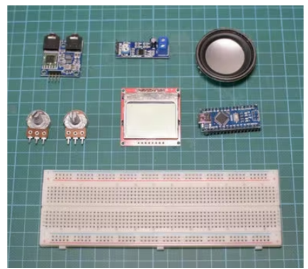
The parts needed to build this project are as follows:
Arduino Nano
FM radio module
Nokia 5110 LCD
10K Potentiometer
Audio Amplifier
3W Speaker
Large breadboard
Audio cable
Jumper Wires
3 in 1 cable
FM transmitter
Power Bank
Step 2: Nokia 5110 LCD Screen
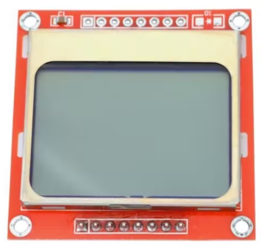
The Nokia 5110 is my favorite display for Arduino projects.
The Nokia 5110 is a basic graphic LCD screen, originally intended for mobile phone screens. It uses the PCD8544 controller, which is a low-power CMOS LCD controller/driver. As a result, the display has impressive power consumption.
It uses only 0.4mA when it's on, but with the backlight disabled. It uses less than 0.06mA in sleep mode! That's what makes this display one of my favorites. The PCD8544 connects to the microcontroller via a serial bus interface. This makes the screen very easy to use with an Arduino. You only need to connect 8 wires.
Step 3: TEA5767 FM Radio Module
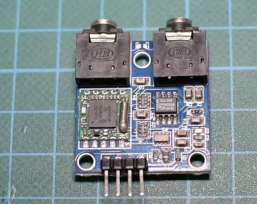
This project is built around this FM Radio module.
This module uses the TEA5767 radio chip. This chip uses the I2C interface, so it can be used directly with the Arduino. On the module, we can also find an audio amplifier. However, it should be noted that this is a headphone amplifier, so we cannot connect a speaker directly to the output of the module. Because the audio signal is very weak, we need to amplify it first. In addition, the volume emitted by the module cannot be controlled through software, so we will use a potentiometer later. There are two headphone interfaces on the module, one is the antenna interface and the other is the standard headphone output interface. The module comes with a small antenna, but you can easily build your own antenna if you want.
Step 4: Connect the components
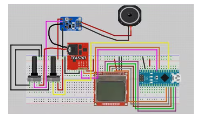
Now let's build the circuit according to this schematic.
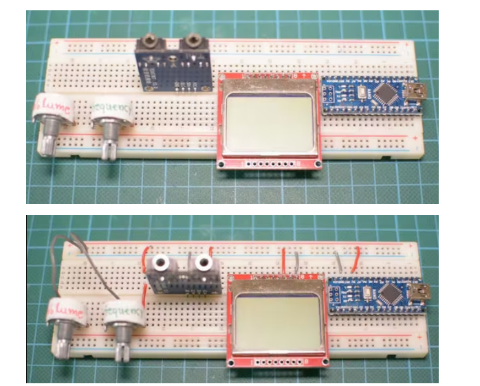
First, place all the parts on the breadboard. We connect the ground pin of each part to the ground rail of the breadboard and the Vcc pin of each part to the positive rail of the breadboard, except for the potentiometer that controls the volume. After that, connect the radio module. The SLC pin is connected to the analog pin 5 of the Arduino Nano and the SDA pin is connected to the analog pin 4. Now we connect the middle pin of the potentiometer to the analog pin 0. Using this potentiometer, we will select the frequency.
Now we need to connect the volume potentiometer to control the volume. I used an audio cable. I plugged one end of the cable into the audio output of the module. Next, I cut the other end to find 4 wires inside the cable. The module outputs stereo, but this time we are only using one audio channel. So, I only connected two wires. One of them is GND and the other is the audio signal that needs to be amplified. The audio signal wire is connected to the input pin of the volume potentiometer. The middle pin of the potentiometer is the output audio signal.
To amplify the audio signal, I used this module that uses the LM386 amplifier chip. The audio signal goes into this pin and the ground pin of the audio cable goes into this pin. Now, all we have to do is to power the module. So we connect this pin to the positive rail of the breadboard and this pin to the negative rail of the breadboard. The only thing we have to do now is to connect a small speaker to the output of the module like this. With this small potentiometer, we can control the amplification of the signal. Now, all we have to do is connect the Nokia 5110 display.
Connect Nokia 5110 LCD display
RST goes to digital pin 12 of the Arduino
CE goes to digital pin 11 of the Arduino
DC is connected to digital pin 10 of Arduino
DIN connects to digital pin 9 of the Arduino
CLK goes into digital pin 8 of the Arduino
VCC goes to Arduino 3.3V
LIGHT connect to Arduino GND (backlight on)
GND to Arduino GND
The last step is optional, connect a 330μF capacitor to the breadboard like this to reduce noise on the audio signal.
If we start the project now, we can see that the splash screen is displayed for 3 seconds, and then, we can hear the sound from the speaker. But the sound quality of the speaker and this audio amplifier is not the best. However, if we use another commercial speaker with an embedded amplifier, the sound quality is perfect. So, the output signal of the module is perfect, but the amplifier and speaker I used reduced the sound quality, so we can look for better quality. Now that we have built the hardware, let's take a look at the software side of the project.
Step 5: Project Code
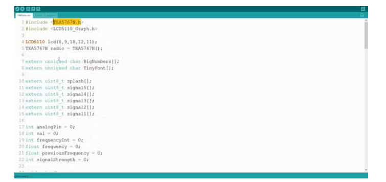
In this project we are using two libraries. I am using Nokia5110 Graphics Library and TEA5767 FM chip's library.
Here's how the code works. First, we initialize the radio module and display and show a three second splash screen. I designed this splash screen in Photoshop.
void setup() {
radio.setMonoReception();
radio.setStereoNoiseCancelingOn();
initScreen();
showSplashScreen();
Serial.begin(9600);
}
Next, in the loop function, we read the value from the potentiometer that controls the frequency every few milliseconds. We get the analog value from the potentiometer and map it to a frequency value. Since we are reading an analog value, the value is not constant; it can go up or down slightly even if we don't turn the potentiometer.
frequencyInt = map(val, 2, 1014, 8700, 10700); //Analog value to frequency from 87.0 MHz to 107.00 MHz
float frequency = frequencyInt/100.0f;
So, to get a stable frequency, we tune the radio to a different frequency only if the frequency changes significantly. So, if the frequency changes significantly, we tune the radio module to that frequency, we get the signal strength, then print it on the screen, if needed, we print the stereo icon, and finally, we print the selected frequency.
if (frequency - previousFrequency 》= 0.1f || previousFrequency - frequency 》= 0.1f) {
lcd.clrScr();
radio.selectFrequency(frequency);
printSignalStrength();
printStereo();
printFrequency(frequency);
previousFrequency = frequency;
}
This is how the code works, it's simple but works fine.
Step 6: Final Thoughts
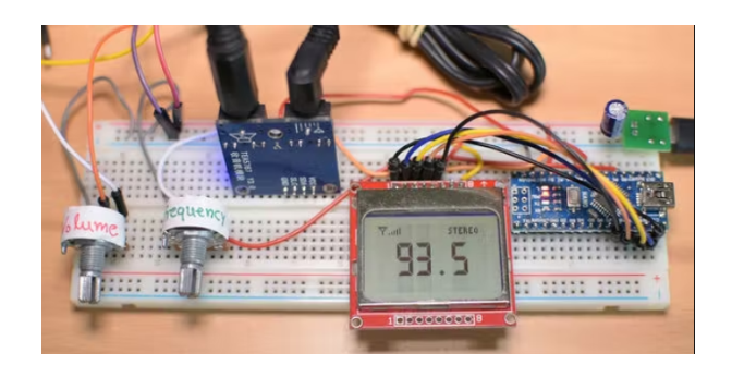
As you can see in about half an hour we can build an FM radio on a breadboard.
The sound quality we get from this project is not great yet. I will be working more on this project to improve it in every area. I want to turn this project into a complete radio with a retro 3D printed enclosure. First, I will try different audio amplifiers and speakers to get good audio quality out of this project. We can also move it away from the breadboard and make a permanent version of it on a prototyping board. It is also possible to design a case for this project to make it look like a radio. Of course, the code for the project also needs a lot of improvements and tweaks. One feature I would like to add is a fine tuning feature which will further improve the sound quality.
This project requires about 50mA of current when the display's backlight is disabled. We can further reduce the current with some software and hardware tricks so that this project can be powered by batteries. I think the results will be impressive and I can't wait to see this project finished on my desk. This project is just the beginning.
- How to Build a Simple FM Radio Receiver on a Breadboard
- The main characteristics, advantages and disadvantages of IoT protocols
- DIY a network router
- Wireless transmission of integrated TV signals for amateur productions
- The production of a crystal oscillator frequency-controlled broadband FM transmitter
- MICRFl04 ASK 470~300 MHz Transmitter
- WE800 FM/FSK 1~0.1 GHz Transmitter
- QMR1/QMR2 AM/FM 868/433.92 MHz Receiver Module
- Common RF receiving circuit design for toys (3 high-frequency parts)
- AT86RF211 FSK 950~400 MHz transceiver
- Do you know about the miniature infrared receiver with sensitivity and noise suppression capabilities?
- Ultrasonic remote control receiver
- Transistor common base mixing circuit commonly used in FM radio frequency conversion circuits
- FM radio high frequency amplification and mixing circuit
- USB communication circuit
- Tuning circuit for FM radio circuit
- Indoor unit communication circuit
- Two-way communication circuit circuit diagram
- MC3367 Monolithic FM Radio
- CAN bus communication circuit


 京公网安备 11010802033920号