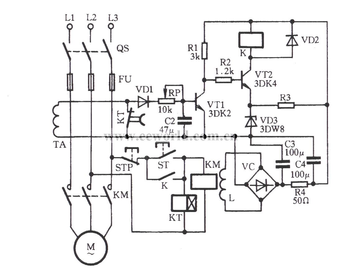
Zero sequence current phase failure protection circuit
Source: InternetPublisher:fish001 Updated: 2013/07/27
 As shown in the circuit in the figure, when the start button ST is pressed, KM is engaged and the motor M is put into normal operation. At this time, the three-phase load of the motor is balanced, the secondary current of the zero-sequence current transformer TA is equal to zero, VT1 is in the cut-off state; VT2 is in the conduction state, the relay K (JR-4 type) is closed, and KM is self-locking. When a phase failure occurs, the induced current generated by the secondary of TA is rectified by VD1, causing VT1 to flip from off to on, and VT2 to flip from on to off (the power supply of VT2 is taken out from the KM coil plus the L winding for 15~ 18V, supplied after VC rectification). When K loses power, it cuts off the power supply of the motor to achieve the purpose of phase failure protection. In order to avoid the unbalanced current during starting, a time relay KT can be added, and its delayed opening normally closed contact will temporarily short-circuit the secondary of TA during the starting process of the motor M. For small-power self-balanced three-phase motors, there is no need to increase KT.
 Latest Control Circuits Circuits
- Servo motor pin diagram/working principle/application
- How to Build a Gesture-Controlled Elevator Prototype Using Arduino Nano
- DIY an electromagnetic levitation device
- A small improvement on the ordinary refrigerator motor starting circuit
- Methods for Eliminating Noise of Brushed DC Motors
- One-way rotation circuit of motor controlled by contactor
- IGBT modules block overcurrent by controlling the gate
- Infrared detection alarm
- Homemade anti-theft watchdog
- Password type motorcycle anti-theft device
Popular Circuits
- Homemade disinfectant circuit
- Multi-channel patrol detection control circuit a
- Assembly line outage monitoring circuit
- Haier KFR-25GW air conditioner control circuit schematic diagram
- Galanz rice cooker control circuit
- Range hood detection control circuit
- Small power electric heater temperature detection control circuit
- Electric heater temperature detection control circuit
- Voltage servo motor and control circuit
- Wide input range non-synchronous voltage mode control circuit


 京公网安备 11010802033920号