Servo motor pin diagram/working principle/application
Source: InternetPublisher:刘德华河北分华 Keywords: Servo Motor Updated: 2025/01/10
Servo motors have a unique property of turning to a specific angle (0, 90, 180) depending on the pulse width of the input signal. These servo motors are widely used in robotic applications, machinery control, etc. Usually a microcontroller will be used to control the servo motor but occasionally you will find some other ICs used for this purpose. This article explains the working and principle of a servo motor.
Pin Diagram:

Internal servo motor:
Inside this motor, you will find a simple DC motor, a potentiometer, and a control circuit that regulates the movement of the DC motor. Every time the motor moves, it changes the resistance in the potentiometer that is fed into the control circuit. In this way, the control circuit can calculate how much movement the DC motor has experienced and its direction. This is described as the feedback mechanism used in the operation of a servo motor.
Working principle of servo motor:
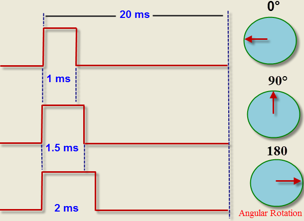
As mentioned earlier, a stepper motor rotates at a specific angle depending on the width of the input pulse. Also, the frequency of the input pulse should match the specifications mentioned in its datasheet. Here, we will mention a hobby servo motor, which operates at a frequency of 50Hz or a time period of 20ms.

The timing diagram above shows the rotation angle relative to the input pulse width. If the high level time in the control signal is 1ms, 1.5ms and 2ms, the motor will rotate to the specified position as specified in the timing diagram.
0, 90 and 180 degrees. These pulses are fed to the control circuit of the servo which in turn controls the movement of the motor.
Not every servo has the same operating specifications (frequency and time period). You must check the datasheet provided by the manufacturer to find out for the servo you are going to use.
application:
Toy cars and airplanes.
robot.
Industrial Applications
Mechanical control.
Manufacturing plants, etc.
- Use your smartphone to turn on/off the power in your home
- What are the challenges in designing a permanent magnet linear generator?
- Manual automatic air compressor control circuit
- Star-delta step-down starting control circuit for squirrel cage asynchronous motor
- Motor control circuit for starting and running without phase loss
- Methods for Eliminating Noise of Brushed DC Motors
- Add one more component to improve the phase failure protection function
- Electric vehicle battery charging protection circuit
- Homemade short circuit alarm device
- Vibration anti-theft alarm circuit
- Pyroelectric automatic door control circuit
- Multi-channel patrol detection control circuit c
- Mobile phone camera flash control circuit
- PLC chain alarm control circuit used in production process
- Haier KFR-25GW air conditioner control circuit schematic diagram
- Typical operation display circuit
- Relay control circuit a
- Timing and fire power control circuit
- Temperature detection control circuit of electric hot water bottle
- DC motor forward and reverse control circuit


 京公网安备 11010802033920号