DIY an electromagnetic levitation device
Source: InternetPublisher:通通 Keywords: Magnetic levitation electromagnetic coil Hall effect sensor Updated: 2024/12/19
This electromagnetic levitation device is cool and can make an exciting and fun anti-gravity project to build. The device can make something float without any visible support, just like an object swimming in free space or air. In order for this device to work, you need to attract an object with an electromagnet, but when it gets very close to the electromagnet, the electromagnet should fail and the attracted object will fall due to gravity and attract it again before the falling object falls completely due to gravity and the process continues. This project is similar to our ultrasonic acoustic levitation, but here we will use electromagnetic waves instead of ultrasound.
Now back to this concept, it is impossible for humans to turn the electromagnet on and off because the switching process must happen very quickly and at a specified time interval. So we built a switching circuit to control the electromagnet to achieve electromagnetic floating.
Required Components

Magnetic levitation circuit diagram
The complete maglev schematic is shown below. As you can see, it consists of only a few commonly available components.
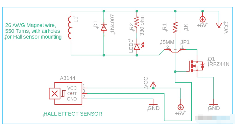
The main components of this DIY magnetic levitation circuit are the Hall Effect Sensor and MOSFET transistor and a solenoid coil. We have previously built other interesting projects using solenoid coils, such as a mini Tesla coil, a solenoid coil gun, etc.
We use Irfz44N N-channel Mosfet for the first switch and turning on/off the electromagnet. Irfz44n / any N-channel MOSFET or similar (NPN) powerful transistor can be used for this purpose, which has high current handling capability like TIP122 /2N3055 etc. Irfz44N transistor is chosen because it is commonly used in microcontroller projects for 5V operation and is easily available in the local market. On the other hand, it has a drain current handling capability of 49A at a temperature of 25 degrees. It can be used for various voltages.
First I tried and tested the circuit and the whole project on a 12 volt configuration, but I found that both my solenoid coil and MOSFET were getting very hot, so I had to switch back to 5 volts. I did not notice any differences or issues occurring, and the MOSFET and coil were at normal temperatures. Also, the Mosfet does not require a heat sink.
Resistor R1 is used to keep the MOSFET gate pin voltage high (like a pull-up resistor) to get the proper threshold voltage or trigger voltage. But when the neodymium magnet is close to the center mounted Hall effect sensor (in the middle of the electromagnet) or the neodymium magnet is within the range of the Hall effect sensor, our circuit should provide a negative output to the MOSFET gate pin. As a result, the pin/control pin voltage drops, indicating the LED and the MOSFET drain pin output of the electromagnet also drops and it is disabled. When the object with the neodymium magnet attached falls or drops due to gravity, the neodymium magnet will be out of the range of the Hall effect sensor and the Hall effect sensor does not provide any output at this point. The MOSFET gate pin goes high and quickly triggers (for R1 resistor the control pin/gate pin is already high) quickly energizing the electromagnet coil and attracting the object with the neodymium magnet attached. This cycle continues and the object remains hanging.
R2 330ohm resistor is used to light up the LED at 5v (indicator LED) and to limit the voltage and current for LED protection. D1 diode is nothing but feedback blocking diode used in every coil device like relay for reverse feedback voltage blocking.
Building a Magnetic Levitation Circuit
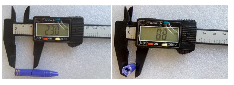
Start by building the solenoid coil. For the air hole solenoid, first you need to make a frame or body for the electromagnet. To do this you will need an old pen with a diameter of about 8 mm that already has a center hole (in my case I measured the diameter with a vernier ruler). Mark the desired length with a permanent marker and then cut into lengths of about 25 mm.
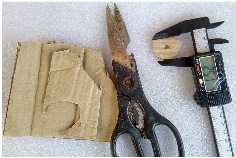
Next, take a small piece of cardboard/any stiff paper material or you can use plexiglass cut two pieces around a center hole of about 25mm diameter as shown in the picture below.
Fix everything with the help of "feviquick" or any strong glue. In the end, the frame should look like this.
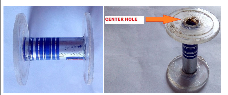
If you are too lazy to do this you can just grab an old soldering wire stand.
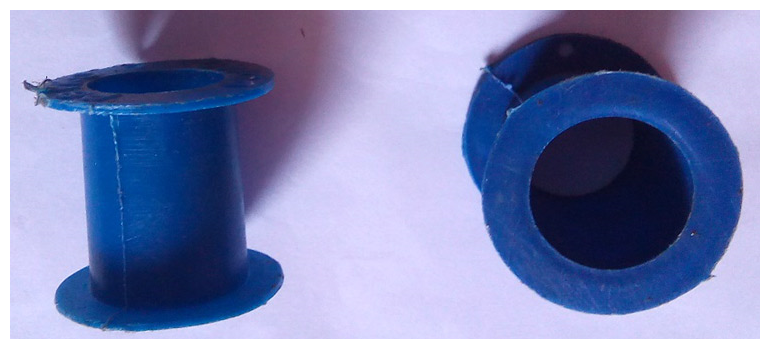
The electromagnet frame is ready. Now proceed to make the electromagnet coil. First, make a small hole on one side of the winding diameter and fix the wire. Start winding the electromagnet and make sure it turns about 550 times. Each layer is separated by cello tape or other type of tape. If you are too lazy to make the electromagnet (in my case, the one I made also has the advantage of using 5v), you can make it from a 6v or 12v relay, but you should be careful, your Hall Effect Sensor A3144 only accepts 5V maximum. Therefore, you need to use a LM7805 regulator IC to power the Hall Effect Sensor.
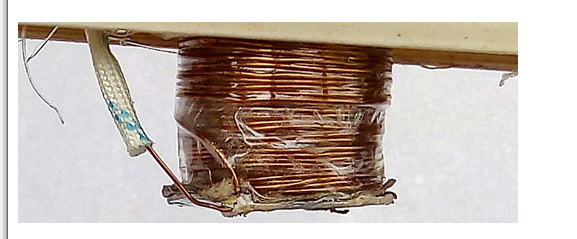
When your center air core solenoid coil is ready, set it aside and go to step 2. Line up all the components and solder them on the Vero board as you can see in the pictures here.
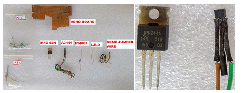
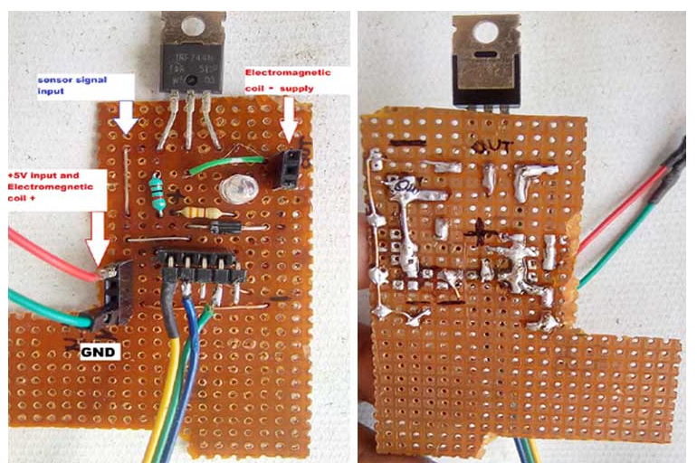
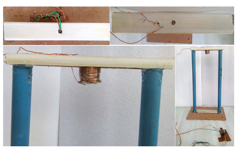
To fix the electromagnetic coil and the Hall Effect sensor device, a bracket was needed due to the alignment of the coil's state and the sensor device was important to suspend the object stably under gravity. I arranged two tubes, cardboard and a small piece of PVC junction box. To mark the required lengths I used a permanent marker and for cutting I used a hand saw and a knife. And fixed everything with the help of glue and a glue gun.
Make a hole in the middle of the PVC junction box and fix the coil with glue. After this, fold the sensor. Place it inside the hole of the electromagnetic coil. Remember that the distance of the suspended object (with the neodymium magnet attached) from the electromagnetic coil depends on how far the sensor is pushed into the center hole of the electromagnet. The Hall Effect sensor has a specific sensing distance that should be within the range of electromagnetic attraction to perfectly suspend the object. Our homemade electromagnetic levitation device is now ready.
Working and Testing the Magnetic Levitation Circuit
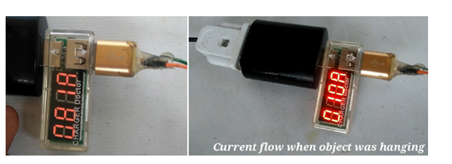
Fix the control board with cardboard using double sided tape. Connect the bracket well with the help of cable ties. Make all the connections with the control circuit. Put the sensor inside the center hole of the electromagnet. Adjust the perfect position of the Hall Effect sensor inside the electromagnet and set the maximum distance between the electromagnet and the neodymium magnet. The distance may vary depending on the attraction of your electromagnet. Power it with a 5V 1Amp or 2Amp mobile charger and do the first test of how the project works.
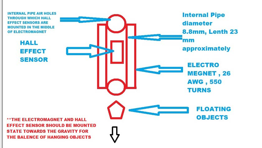
Please pay careful attention to some important points about this electromagnetic levitation project. The alignment of the coil and sensor setup is essential. So, the object needs to be suspended stable and straight towards the direction of gravity. A stable system means that something is balanced. For example, consider a long stick held from the top. It is stable and hanging straight down towards gravity. If you push the bottom away from the straight down position, gravity will tend to pull it back to a stable position. So, from this example, you can clearly understand how important the straight alignment of the coil and sensor is. It is important to keep the object upright for a long time without falling, and that is why we made a stand for this project. For your better understanding,
If you want to increase the distance of the suspended object from the electromagnet, you will have to increase the power and range of attraction of the electromagnet and change the arrangement/position of the sensors.
If you want to suspend a larger object, you have to increase the electromagnetic power. To do this, you need to increase the GAUGE and number of turns of the electromagnetic wire, and you also need to increase the number of neodymium magnets connected to the suspended object.
Bigger electromagnets draw more current, my circuit currently only works at 5V, but in some cases it may be necessary to increase the voltage depending on the coil parameters.
If you use a 12V relay coil or any high voltage high power solenoid coil, don't forget to use the LM7805 voltage regulator for the A3144 Hall Effect Sensor.
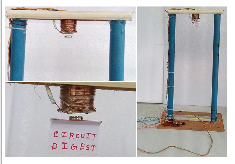
The following image shows how our project will work when it is completed. I hope you understood this tutorial and learned something useful.
- Analysis of the working principle of car garage door lights
- Servo motor pin diagram/working principle/application
- Build a Smart Garage Door Opener Using a Raspberry Pi
- DIY an electromagnetic levitation device
- Manual automatic air compressor control circuit
- JDB-LQ-TQ/2 motor full voltage starting circuit
- Motor self-starting circuit
- Design and analysis of touch delay switch circuit composed of CD4011 and CD4001
- Amplitude and phase detection leakage protection device designed and manufactured using PIC16C711A
- A novel and practical power line anti-theft and cutting alarm circuit
- Multi-channel patrol detection control circuit b
- fire smoke control circuit
- Water and electricity saving infrared control circuit
- Photocell amplification control circuit
- Switching regulated power supply circuit
- Multi-pole leakage protector circuit b
- Multi-pole leakage protector circuit a
- Digital current loop control circuit
- Voltage servo motor and control circuit
- Wide input range non-synchronous voltage mode control circuit


 京公网安备 11010802033920号