High-power switching—an important task of transistors
Source: InternetPublisher:闪电杰克 Updated: 2020/03/02
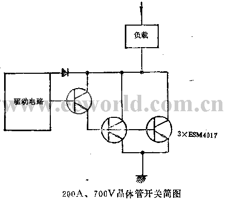
(1) Control high power. Today’s power transistors can control hundreds of kilowatts of power. There are many advantages to using power transistors as switches, mainly: (1) Easy to turn off, requiring few auxiliary components, (2) Rapid switching , can work at very high frequencies, (3) The available devices have a withstand voltage range from 100V to 700V. A few years ago, the switching capacity of transistors was less than 10kW. Currently, it can control power up to hundreds of kilowatts. This is largely due to the combined efforts of physicists, technicians and circuit designers to improve the performance of power transistors. Such as (1) the increase in the effective chip area of switching transistors, (2) technical simplification, (3) the combination of transistors - Darlington, (4) the advancement of base drive technology for high-power switches. , (2) The transistor power switch that directly works on the rectified 380V mains is shown in Figure 1. The power switch is composed of three transistors and has the ability to switch 200A current at a voltage of 700V. In this high-power Darlington switch, two 50A, 700V transistors are connected in parallel and driven by a third identical transistor.
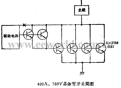
 If larger load currents need to be switched, more transistors can be used in parallel. Figure 2 shows a 400A, 700V high-power switch using a total of six power transistors.
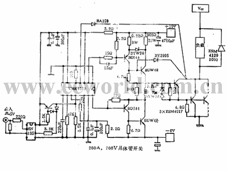
 Transistor compounding (Darlington) and paralleling are both effective ways to increase the switching capabilities of transistors. In such high-power circuits, the main problem is wiring. High switching speeds can produce relatively high interference voltages on very short connecting lines. (3) High performance achieved by simple and optimized base drive Today's base drive circuit not only drives the power transistor, but also protects the power transistor, which is called "non-centralized protection" (in contrast to centralized protection). In the above application example, the functions of the integrated drive circuit include: (1) Turning on and off the power switch; (2) Monitoring the auxiliary power supply voltage; (3) Limiting the maximum and minimum pulse width; (4) Thermal protection; (5) ) monitors the saturation voltage drop of the switch. Application examples are as follows:
 It can be seen that switching high power with a power transistor is as easy as switching low power.
 If larger load currents need to be switched, more transistors can be used in parallel. Figure 2 shows a 400A, 700V high-power switch using a total of six power transistors.
 Transistor compounding (Darlington) and paralleling are both effective ways to increase the switching capabilities of transistors. In such high-power circuits, the main problem is wiring. High switching speeds can produce relatively high interference voltages on very short connecting lines. (3) High performance achieved by simple and optimized base drive Today's base drive circuit not only drives the power transistor, but also protects the power transistor, which is called "non-centralized protection" (in contrast to centralized protection). In the above application example, the functions of the integrated drive circuit include: (1) Turning on and off the power switch; (2) Monitoring the auxiliary power supply voltage; (3) Limiting the maximum and minimum pulse width; (4) Thermal protection; (5) ) monitors the saturation voltage drop of the switch. Application examples are as follows:
 It can be seen that switching high power with a power transistor is as easy as switching low power.
 Latest Control Circuits Circuits
- Servo motor pin diagram/working principle/application
- How to remotely control devices using ESP8266 and LPC2148
- Peripheral circuit of automotive motor controller power supply chip
- How to build a simple tachometer using an infrared reflectance sensor
- A small improvement on the ordinary refrigerator motor starting circuit
- Controlling stepper motors with wireless remote control transceiver and PE-51 board
- Motor control circuit for starting and running without phase loss
- Infrared detection alarm
- Water supply reminder after water outage
- High-sensitivity and high-loudness burglar alarm circuit
Popular Circuits
- Homemade disinfectant circuit
- Multi-channel patrol detection control circuit a
- Assembly line outage monitoring circuit
- Haier KFR-25GW air conditioner control circuit schematic diagram
- Galanz rice cooker control circuit
- Range hood detection control circuit
- Small power electric heater temperature detection control circuit
- Electric heater temperature detection control circuit
- Voltage servo motor and control circuit
- Wide input range non-synchronous voltage mode control circuit


 京公网安备 11010802033920号