Design of an air quality monitoring system using LinkIt ONE
Source: InternetPublisher:JFET Keywords: Portable Devices Monitoring Systems LinkIt Updated: 2024/12/31
The project monitors temperature, humidity, pressure, air quality, dust particle concentration online and detects fire using LinkIt ONE and sensors .
background
Half of the world’s population currently lives in cities, and within twenty years, nearly 60% of the world’s population will be city dwellers. Urban growth is fastest in the developing world, with cities adding an average of 5 million new residents every month. The explosive growth of urban populations has brought unprecedented challenges, one of the most serious environmental issues being air pollution. We plan to create an Air Quality Box, which will be a compact, portable solution for monitoring air quality as well as various other parameters such as temperature, humidity, dust concentration and pressure, which can be accessed through the cloud.
We would even like to go a step further and integrate the functionality of fire detection as well as detecting the levels of different gases in the air, thus being fully capable of monitoring air quality. This, combined with integrated cloud connectivity, will make data collection easier and therefore easy to use for analysis across multiple sites and data levels to identify sources of pollution in individual cities and pockets within cities.
Step 1: Set up LinkIT
Step 1: Software Setup
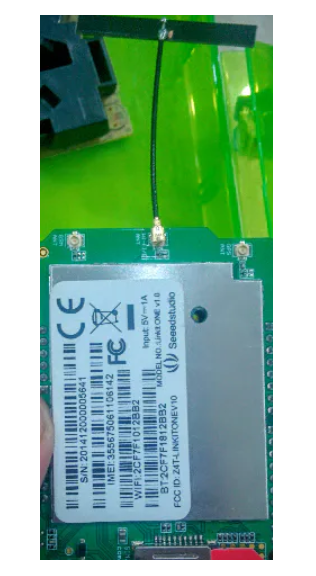
Download Arduino 1.5.7, then download the latest SDK from LinkIT . This will install all the drivers needed, and you can then try running the example projects from the SDK to check that everything is working.
Step 2: Hardware Setup
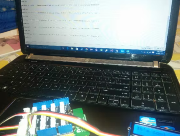
Once you have installed the compatible software and drivers, the LinkIT ONE does not involve any major setup. Simply connect the board to your laptop , see if it is recognized and try any of the examples to check if it works properly.
Note: Since this is a portable solution, it can easily be placed inside a small box or container and set up anywhere. We have currently used the Seeed Grove kit box for this purpose.

Once all this is done, make the connection and copy the code, edit it according to your WiFi settings (i.e. SSID and key), and upload it to the Arduino IDE.
Note: You can also store the key and SSID parameters for your WiFi in a separate file called WiFi.txt, store it in the LinkIT ONE's storage, and instruct the board to retrieve the credentials from there. The code for the same is beyond the scope of this project.
Step 3: Test the code
Open the serial monitor and you will be able to see a number of different readings displayed, namely - humidity, pressure, dust concentration and air quality. The LCD screen will display the temperature in a color coded format, i.e. in relatively cool or cold temperatures it will display the temperature reading in blue and if hot it will display it in red. For more information on how to set up the color display in detail, refer to - https://www.hacks ter.io/rishabhbanga/grove-starter-kit-with- intel-galileo-gen-1-getting -started-4dd5f1?ref=user&ref_id=9845&offset=3.

Step 4: Put it in the cloud
The next step is to integrate cloud connectivity and display all current data shown in the serial monitor on the cloud so that the data can be accessed anywhere and at any time.

For this purpose, I will be using MediaTek's own cloud platform. The setup is divided into two parts:
1) Create a prototype to control and monitor data using data channels.
2) Create a test device to support hardware connection and data transfer.

Once you run the program, humidity, temperature, altitude, and pressure values will start to display. The air quality display and dust concentration require some adjustments.
Each of these controls has a shortcut menu. Opening the shortcut menu for a data channel and selecting the Show History option will display all face and current values for each data channel.

Step 5: Future expansion plans
1. Design a compact housing for easy use and transportation.
2. Integrate a siren (buzzer) that will sound in case of fire.
3. Use AWS instead of cloud services.
WiFi Connection Arduino:
#include
#include
#include
#include
#include
#define WIFI_AP "" //WiFi SSID
#define WIFI_PASSWORD "" //WiFi Key
#define WIFI_AUTH LWIFI_WPA2 //Authentication Mode
#define per 50
#define per1 3
#define DEVICEID "" // Device ID given by cloud sandbox
#define DEVICEKEY "" //Device key given by cloud sandbox
#define SITE_URL "api.mediatek.com" //the site of the API
LWiFiClient c; //wifi client
LWiFiClient c2;
HttpClient http(c2); //http client
unsigned int rtc; //real-time clock
unsigned int lrtc;
unsigned int rtc1;
unsigned int lrtc1;
char port[4]=" ";
char connection_info[21]=" ";
char ip[21]=" ";
int portnum;
int val = 0;
String tcpdata = String(DEVICEID) + "," + String(DEVICEKEY) + ",0";
String TCPCMD_LED_ON = "LED_controller,1"; //tcp command to controll LED ON/OFF
String TCPCMD_LED_OFF = "LED_controller,0";
void setup() {
//initialize
Serial.begin(115200);
LTask.begin();
LWiFi.begin();
Serial.println("Connecting to AP");
while (0 == LWiFi.connect(WIFI_AP, LWiFiLoginInfo(WIFI_AUTH, WIFI_PASSWORD)))
delay(1000);
Serial.println("WiFi succeed");
Serial.println("calling connection");
while (!c2.connect(SITE_URL, 80))
delay(1000);
Serial.println("Connection to site succeed");
getconnectInfo();
Serial.println("getConnectionInfo succeed");
connectTCP();
Serial.println("connectTCP() succeed");
}
- Design of an air quality monitoring system using LinkIt ONE
- How to Build a Simple Yet Powerful MP3 Player
- Building a Dehumidifier for a 3D Printing Dry Box
- Share a fire sensor solution using MLX90640
- Production of electric mosquito killer
- How to use RFID to create an automatic roll call attendance system
- How to design a mask disinfection device using infrared temperature sensors
- How to use the MP3 player from CATALEX
- How to build an internet-connected traffic meter
- How to Design a Wireless Remote Controlled Two-Wheeled Robotic Rover Using ESP8266 and Arduino Uno
- Portable device charging power circuit design
- Portable device charging power circuit design
- How does an optocoupler work? Introduction to the working principle and function of optocoupler
- 8050 transistor pin diagram and functions
- What is the circuit diagram of a TV power supply and how to repair it?
- Analyze common refrigerator control circuit diagrams and easily understand the working principle of refrigerators
- Hemisphere induction cooker circuit diagram, what you want is here
- Circuit design of mobile phone anti-theft alarm system using C8051F330 - alarm circuit diagram | alarm circuit diagram
- Humidity controller circuit design using NAND gate CD4011-humidity sensitive circuit
- Electronic sound-imitating mouse repellent circuit design - consumer electronics circuit diagram


 京公网安备 11010802033920号