What is Harmonic Distortion?
Source: InternetPublisher:smallembedded Keywords: Power system harmonics nonlinearity Updated: 2024/05/27
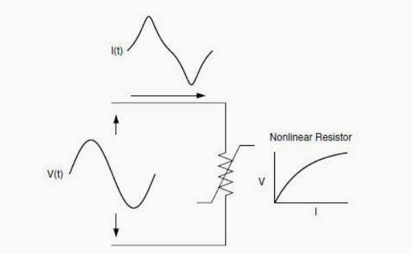
Harmonic distortion is caused by nonlinear devices in the power system. A nonlinear device is one where the current is not proportional to the applied voltage. Figure 1 illustrates this concept by applying a sinusoidal voltage to a simple nonlinear resistor, where the voltage and current vary according to the curves shown. Although the applied voltage is a perfect sinusoid, the resulting current is distorted.
Increasing the voltage by a few percent may double the current, and give it a different waveform. This is the source of most harmonic distortion in power systems.

Figure 1 Current distortion caused by nonlinear resistance.
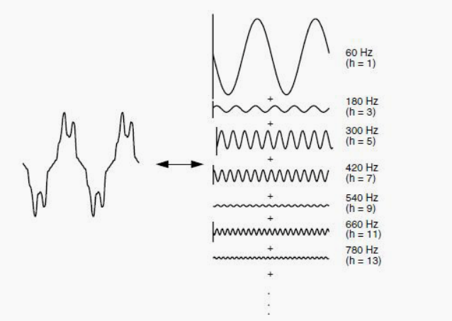
Figure 2 illustrates that any periodic distortion waveform can be represented as a sum of sinusoids. When a waveform is identical from one cycle to the next, it can be represented as a sine wave where the frequency of each sine wave is an integer multiple of the fundamental frequency of the distortion wave. Such multiples are called harmonics of the fundamental, hence the name of this topic.
This sum of sinusoids is called a Fourier series, named after the great mathematician who discovered the concept.
Because of the above properties, the Fourier series concept is commonly used to analyze harmonic problems. Now the system can be analyzed separately at each harmonic. In addition, it is much simpler to find the system response of the sinusoid of each harmonic separately compared to the entire distorted waveform. The outputs at each frequency are then combined to form a new Fourier series from which the output waveform can be calculated if necessary.
Typically, we are only interested in the amplitude of the harmonics. When the positive and negative half-cycles of the waveform have the same shape, the Fourier series contains only odd harmonics. This provides a further simplification for most power system studies, since most common harmonic-generating devices will look the same in both polarities. In fact, the presence of even harmonics is often a clue that there is a problem with the load device or the sensor used to measure it.
There are notable exceptions, such as half-wave rectifiers and arc furnaces, where the arc is random.

Figure 2 Fourier series representation of distorted waveform
Typically, in power system analysis, higher-order harmonics (above the 25th to 50th range, depending on the system) are ignored.
While they may interfere with low power electronics, they generally do not damage the power system. It is also difficult to collect data accurate enough to simulate the power system at these frequencies. A common exception is when there are system resonances in the frequency range. These resonances can be excited by notches or switching transients in electronic power converters. This causes multiple zero crossings in the voltage waveform, which can interfere with timing circuits. These resonances often occur on systems that have underground cables but no power factor correction capacitors.
If a power system is conventionally described as series and parallel elements, the vast majority of nonlinearities in the system are in the parallel elements (i.e., LODs). The series impedance of a power delivery system (i.e., the short-circuit impedance between the source and the load) is very linear. In a transformer, the source of harmonics is also the parallel branch of the normal "T" model (the magnetizing impedance); the leakage impedance is linear.
Therefore, the major source of harmonic distortion will ultimately be the end user load. This is not to say that all end users that experience harmonic distortion are themselves large sources of harmonics, but rather that harmonic distortion generally originates from some end user's load or combination of loads.
- How does a series arrangement of Zener diodes affect the electrical behavior?
- What is an ac to dc transformer in circuit design
- Ideal characteristics of operational amplifiers/pin configurations/gain types/primary applications
- Capacitance detection circuit configuration, how to deal with low frequency and high frequency noise?
- What types of force sensors are there?
- What is a Demultiplexer
- NE5532 standard linear preamplifier IC circuit features and application schematics
- Presettable 8-bit counter circuit
- Square wave frequency multiplier (SN15844N, SN7400N)
- Digital control frequency division circuit composed of MC4018
- Primary circuit diagram of a factory's power system
- TBB series is the best installation circuit solution
- Third harmonic thyristor automatic excitation device circuit b
- Third harmonic thyristor automatic excitation device circuit a
- Third harmonic excitation circuit
- Hearing sense actuator (b) composed of NE571
- Hearing sense actuator (a) composed of NE571
- 73.333MHZ third harmonic circuit diagram
- DC isolation circuit to suppress harmonics
- 4kHz harmonic generator


 京公网安备 11010802033920号