Car ice warning circuit sharing
Source: InternetPublisher:明天见 Keywords: Alarm circuit thermistor Updated: 2025/01/07
Because thermistors are readily available, devices that react to changes in atmospheric or fluid heat are easy to build. This automotive ice warning circuit explains how to implement a thermistor like a transducer in a circuit that flashes a warning light continuously once the atmospheric temperature drops to around 0°C.
Why icy roads are dangerous
Ice, especially black ice, is one of the most dangerous conditions that drivers can easily encounter during the colder months. Even if it doesn't seem too cold outside, snow can still fall onto the streets and may be slowly thawing. Black ice can be particularly dangerous at night and in the mornings, mainly because it looks like wet streets instead of icy. Black ice is very elusive, which means that for vehicles, it can easily lead to skids and accidents.
Keeping this in mind, this circuit was developed and can be used to get warning signals about temperatures that may drop to frost levels. Or, as this project explains, the circuit may be used to warn car drivers about icy street conditions.
design
In addition to a couple of bipolar transistors, one npn and one pnp type, the circuit employs 3 other forms of semiconductor devices. First, the thermistor, which involves a small amount of semiconductor substance, is actually a glass capsule type negative temperature coefficient (NTC) type.
Its tiny size helps it respond quickly to temperature changes, while the glass cover protects the semiconductor from the conductive properties of the liquid, which could otherwise produce misleading results.
Note that the NTC thermistor carries a resistance that rises as the temperature drops. Also, the recommended 741 type op-amp IC is used as a sensitive voltage change sensor around the Wheatstone bridge. One of the specific arms consists of the thermistor.
The thermistor can be any 100K NTC thermistor.
Finally, LED lights are used as indicator lights for flashing warning signals. Such lights are compact, rugged, and consume virtually no current to illuminate.
Circuit Description


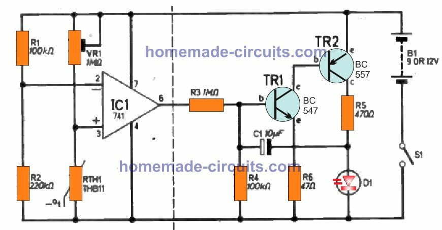
The entire circuit for the "Frost" alarm is shown in the figure above. It is driven by the voltage of a 12V car battery. Alternatively, for other applications, a 9V battery may be sufficient to run the circuit.
The circuit basically consists of several elements broken down by the dotted lines. The left side of the line shows a temperature sensitive Wheatstone bridge, the output of which is sensed by an op amp operating like a differential amplifier.
To the right of the dotted line there is a two-transistor oscillator that oscillates the LED once the thermistor extends to a preset temperature.
The Wheatstone bridge consists of resistors R1 and R2, which clamp the voltage on the inverting terminal of the op amp to about 12 V with respect to ground (for an 8 V battery). Preset VR1 and thermistor RTH1 create the second arm of the bridge.
This is because the thermistor is an NTC specification and you will find that as the temperature drops its resistance increases, causing the voltage at pin 3 to rise proportionally.
When this voltage happens to cross the reference level at pin 2, the output of the op amp changes state and flips from around zero to a positive value of several volts.
The temperature at which the output is significantly positive can be determined by fine-tuning preset VR1. The rapid increase in voltage at the output of the op amp turns the oscillator circuit on, as shown to the right of the dotted line. Resistor R3 uses this voltage to switch the base of transistor TR1.
Capacitor C1 helps maintain the positive feedback necessary for low frequency amplitude. pnp transistor TR2 powers the LED at its collector terminal and a series resistor R5 is calculated which goes into
The LED current is limited to below the maximum rating.
The LED flashing frequency is determined to some extent by its own resistance, although it can be adjusted to the desired level by choosing an appropriate amplitude for Cl.
Transistors TRI and TR2 need to be complementary and matched for the circuit to function optimally.
Circuit Assembly
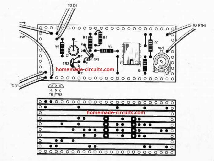
Except for the battery, switch and LED, every component can be assembled on a 0.1 inch matrix Veroboard
on, as shown below, although the actual design will most likely depend on the actual proportions of the parts purchased by the user.

The thermistor should be located away from any possible heat sources or the engine. It should be close to the floor of the car so that it can more easily sense the temperature of a cold patch of ice on the road a foot below.
Thermistors must be protected from possible water splashes or rain, as the cooling effect caused by water evaporation may cause their temperature to suddenly drop below the actual surrounding temperature, resulting in a false alarm.
An effective location for the thermistor is at the rear of the front bumper, but depending on the type of car, a better location may be determined. Once the correct location for the thermistor has been found, the required wire distance between the thermistor and the control circuit needs to be determined.
Be careful when soldering the extension wire to the thermistor, as the soldered joint must be protected with a sleeve to prevent water contact. A sleeve with heat shrink properties is probably the best choice.
The thermistor must be glued to the surface of the short plastic tube to ensure that it is kept away from possible water splashes when air flows around it.
Almost any tiny plastic box will work to enclose the circuit, or it can be safely placed somewhere behind the dashboard of your car. Three sets of output wires should terminate in the box via grommets: a few wires to the battery, 2
1 is connected to the thermistor and 2 are connected to the LED.
Choose a location within the dashboard that is best suited for visualizing the LED flashing. Drill a hole for the LED to pass through so that it can be easily pushed through the plastic washer.
The LED should be connected to the circuit precisely so that TR2 can turn it on properly by forward biasing it.
You can easily identify the LED anode pin with a multimeter set to the Ohm range. Before finally installing the circuit in your car, the results must be confirmed with an actual ice temperature test.
calibration
Crush a little ice in a bowl until it becomes liquid. Make sure the ice is actually in a melted state, this will provide the required 0°C level for the test. If you have access to a thermometer, be sure to verify the temperature with one.
Submerge the thermistor in melted ice and fine-tune the preset resistance until the LED begins to pulsate. Remove the thermistor from the frozen water and you may find that the LED
Eventually it stopped flashing.
Alternatively, you can select a different temperature as the blinking threshold for the LED.
This circuit is very resistant to supply voltage variations and will not cause the LED to flicker at temperatures outside of this setting. Incidentally, resistor R5 also helps to avoid frequent flickering of the LED when the thermistor temperature is just close to the set level. This resistor provides a slow discharge path for the capacitor.
Custom Circuits
If you feel the need to modify the circuit so that it gives an audible warning instead of flashing the LED, you can simply do the following.
Modify the value of C1 to about 0.1μF (a value chosen for the desired frequency) and replace R5 with a small 80 ohm speaker along with the LED. This will connect C1 directly to TR2.
Collector connection.
- Design and selection of electric control valve system drive
- How to Build a Touch-Based Color-Changing Plant Using Arduino
- How to Build a Gesture-Controlled Elevator Prototype Using Arduino Nano
- Perform surgery on the speaker protection circuit
- DC motor drive circuit composed of L293D
- Design and production of radio remote control fan stepless speed regulator
- Temperature control circuit design and analysis
- An experimental model of an infrared radio alarm
- A novel and practical power line anti-theft and cutting alarm circuit
- Multi-channel laser anti-theft alarm circuit
- Call for help alarm circuit
- Lost child alarm circuit b
- Overtemperature alarm circuit 2
- Water shortage alarm circuit 2
- Inductive high voltage alarm circuit 5
- Current transformer secondary open circuit alarm circuit
- One of the inductive high voltage alarm circuits
- Power outage and incoming call alarm circuit 3
- Power outage alarm circuit three
- One of the mains undervoltage and overvoltage alarm circuits


 京公网安备 11010802033920号