Detailed explanation of the working principle of the parking light circuit
Source: InternetPublisher:王达业 Keywords: Car lights Updated: 2025/01/10
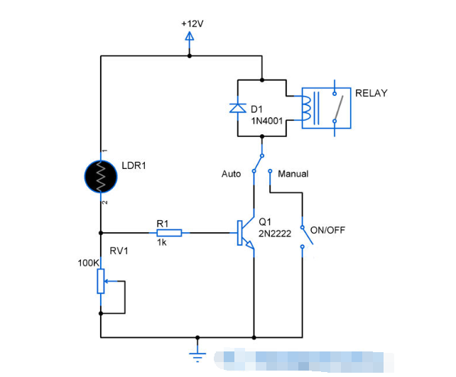
Parking lights are very useful, especially at night. These lights will help you park your vehicle properly in the garage and avoid damage to your vehicle by hitting nearby objects. This parking light circuit uses the beam from the vehicle's headlights to detect incoming vehicles and turn the garage lights accordingly. You can also operate this circuit in manual mode to keep the lights under control.

Working principle of parking light circuit:
This circuit uses a simple LDR to detect the incoming light from the vehicle. It is paired with a simple variable resistor RV1 to form a voltage divider to provide bias voltage to the transistor. The transistor is used as a switch here to turn on/off the relay connected to it. The relay in turn will be used to turn the lamp or any high powered light connected to it.
This circuit can be operated in both automatic and manual modes where a SPDT switch is used to switch the mode. When the automatic mode is selected, the transistor will act as a switch, which is controlled by the LDR and RV1 pair. When light shines on the transistor, this pair automatically turns the transistor and in turn the relay. Meanwhile, in the manual mode, a simple switch is used to turn the relay on and off.
Now to set up the above circuit, the LDR has to be exposed to the light from the vehicle in darkness and RV1 is adjusted until the relay opens. This makes the potential divider section provide bias voltage to the transistor only when the light from the vehicle is incident on the transistor, which makes the relay open at the same moment.
Notice:
Install the entire circuit on the wall and the light from the accident vehicle will be incident directly on the wall.
Take some time to set up the circuit using trial and error.
- Detailed explanation of the working principle of the parking light circuit
- Audio Adapter Cable - Upgrading Car Audio with MP3 Player
- Design of water management system based on Internet of Things
- Battery equalization system and control method thereof
- UCC587x-Q1 power-on false alarm mechanism and initialization precautions
- Secret code lock circuit
- Two-channel SL320 level indication circuit
- SCR control buzzer circuit
- JS13 type transistor time relay circuit
- Analog counter circuit circuit diagram


 京公网安备 11010802033920号