Design a pet NFC timer feeder
Source: InternetPublisher:桂花蒸 Keywords: nfc feeder Updated: 2024/12/19
I designed and built this automatic cat feeder to help my diabetic cat control his feeding and prevent my other cat from eating his food. This feeder may be useful to other pet owners who need to monitor their pet's feeding needs.
My cat requires medicated food as well as daily insulin doses, and he will often trick us into feeding him twice, or another cat will eat his food, making it hard to know how much he is actually eating.
I wanted to create a closed feeder that could detect which cat was at the feeder and then open for the correct cat. My first thought was to use NFC tags on their collars so I could tell them apart. However, effective proximity of NFC tags is problematic as they only activate within a few millimeters of the tag. After going through several other ideas, including reading the microchip on the back of them , I decided the easiest way to tell my two cats apart was by weight.
I found a project on Instructables for creating a bathroom scale using an Arduino Uno, and after successfully building that project, I decided to create this one. The scale is accurate to a tenth of a pound, but your animal will move around a lot, so we'll try to differentiate between about half a pound or a quarter of a kilogram.
I created a prototype and went through a dozen or more design ideas before settling on this solution.
This is a moderately difficult project. It requires the use of some basic power tools, soldering, a fair amount of 3D printing, sanding, and gluing. All of the code for the project is provided, along with instructions on how to modify the code.

Supplies
Tools needed: 3D printer, computer, drill, soldering iron, screwdriver set, pliers, needle-nose pliers, sandpaper, Dremel tool (optional), heat gun, cyanoacrylate liquid glue, hacksaw, voltmeter.
Step 1: 3D Printing
Print all custom components starting with the load cell bracket. You will need 4 load cell bases and tops.
Step 2: Build the weighing scale
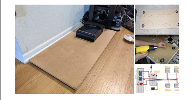
Use a material such as MDF to cut the base of your scale to whatever size you like. Mine is 30” x 15” (76cm x 38cm) and the feeder itself is ~7” x 8.5” (18cm x 21.5cm)
Pre-drill holes using the load cell mount as a guide for the four corners. It will be helpful to mark which load cell is which (top left, bottom left, etc.).
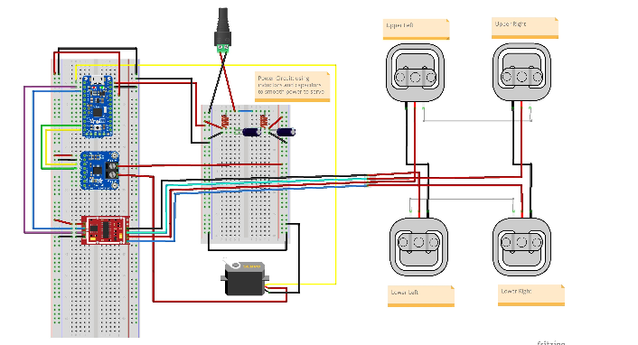
Use the wiring diagram in the picture
1) Connect the load cell wire pair
2) Cut the wires to a certain length
3) Place heat shrink tubing over the wires before removing the outer casing using wire strippers and twisting the pairs together.
Apply solder to the wires, then move the heat shrink tubing over the connection and heat it.
Once the wire pairs are connected you should have four loose red wires, one for each load cell. You will be using a four pin female RGB header connector. Drill a hole large enough for the wire to pass through near the lower left load cell where the red circle is as shown in the picture above. Next, solder and heat shrink the red wire to the correct color wires on the RGB female header following the wiring diagram in the picture. You must connect the correct signal wire to the correct color or your scale will not work. Solder the male connector to the HX711, which is the red chip in the wiring diagram, again making sure all the colors are in the correct order. Also solder the 4 breakout pins to the holes labeled VCC, SCK, DT, and GND.
Project wiring diagram-click to download
Step 3: Scale Calibration and Testing
Next, you will need a breadboard, an Arduino Uno, and some jumper wires.
Sparkfun has a great Arduino program to run, the latest version can be found on GitHub by clicking this link
The first software step is to determine the calibration factors for the scale. To do this, run the following code:
|
/* Example using the SparkFun HX711 breakout board with a scale By: Nathan Seidle SparkFun Electronics Date: November 19th, 2014 License: This code is public domain but you buy me a beer if you use this and we meet someday (Beerware license). This is the calibration sketch. Use it to determine the calibration_factor that the main example uses. It also outputs the zero_factor useful for projects that have a permanent mass on the scale in between power cycles. Setup your scale and start the sketch WITHOUT a weight on the scale Once readings are displayed place the weight on the scale Press +/- or a/z to adjust the calibration_factor until the output readings match the known weight Use this calibration_factor on the example sketch This example assumes pounds (lbs). If you prefer kilograms, change the Serial.print(" lbs"); line to kg. The calibration factor will be significantly different but it will be linearly related to lbs (1 lbs = 0.453592 kg). Your calibration factor may be very positive or very negative. It all depends on the setup of your scale system and the direction the sensors deflect from zero state This example code uses bogde’s excellent library:"https://github.com/bogde/HX711" bogde’s library is released under a GNU GENERAL PUBLIC LICENSE Arduino pin 2 -> HX711 CLK 3 -> DOUT 5V -> VCC GND -> GND Most any pin on the Arduino Uno will be compatible with DOUT/CLK. The HX711 board can be powered from 2.7V to 5V so the Arduino 5V power should be fine. */ #include "HX711.h" #define LOADCELL_DOUT_PIN 3 #define LOADCELL_SCK_PIN 2 HX711 scale; float calibration_factor = -7050; //-7050 worked for my 440lb max scale setup void setup() { Serial.begin(9600); Serial.println("HX711 calibration sketch"); Serial.println("Remove all weight from scale"); Serial.println("After readings begin, place known weight on scale"); Serial.println("Press + or a to increase calibration factor"); Serial.println("Press - or z to decrease calibration factor"); scale.begin(LOADCELL_DOUT_PIN, LOADCELL_SCK_PIN); scale.set_scale(); scale.tare(); //Reset the scale to 0 long zero_factor = scale.read_average(); //Get a baseline reading Serial.print("Zero factor: "); //This can be used to remove the need to tare the scale. Useful in permanent scale projects. Serial.println(zero_factor); } void loop() { scale.set_scale(calibration_factor); //Adjust to this calibration factor Serial.print("Reading: "); Serial.print(scale.get_units(), 1); Serial.print(" lbs"); //Change this to kg and re-adjust the calibration factor if you follow SI units like a sane person Serial.print(" calibration_factor: "); Serial.print(calibration_factor); Serial.println(); if(Serial.available()) { char temp = Serial.read(); if(temp == ’+’ || temp == ’a’) calibration_factor += 10; else if(temp == ’-’ || temp == ’z’) calibration_factor -= 10; |
Once you have calibrated your scale, you can run this example program and then modify it for your own purposes:
|
/* Example using the SparkFun HX711 breakout board with a scale By: Nathan Seidle SparkFun Electronics Date: November 19th, 2014 License: This code is public domain but you buy me a beer if you use this and we meet someday (Beerware license). This example demonstrates basic scale output. See the calibration sketch to get the calibration_factor for your specific load cell setup. This example code uses bogde’s excellent library:"https://github.com/bogde/HX711" bogde’s library is released under a GNU GENERAL PUBLIC LICENSE The HX711 does one thing well: read load cells. The breakout board is compatible with any wheat-stone bridge based load cell which should allow a user to measure everything from a few grams to tens of tons. Arduino pin 2 -> HX711 CLK 3 -> DAT 5V -> VCC GND -> GND The HX711 board can be powered from 2.7V to 5V so the Arduino 5V power should be fine. */ |
Follow the scale calibration sketch in this project and get your calibration factor ex as -9660.0, you will need this data in the following steps.
Step 4: Feeder Body and Cover Assembly
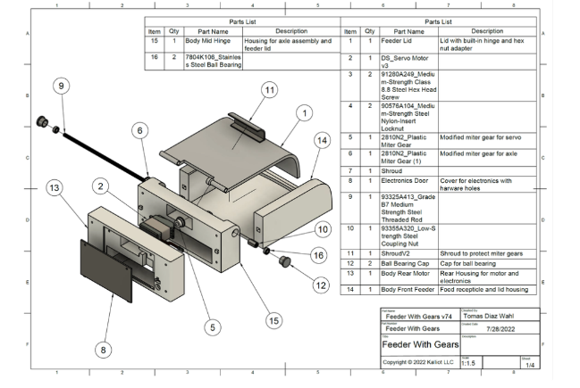
The first step is to attach the feeder cover to the body mid hinge assembly. You will also need the plastic miter gear shaft, M5 connecting nut, and M5 threaded rod. You want to make sure your cover fits between the fins of the hinge mechanism and has clearance without any hiccups or chafing.
Make sure your coupling nut fits very snugly over the hexagonal connector and plastic miter gear on the feeder cap. A snug fit here is very important and there should not be any play. Next, cut the threaded rod to 18cm using a circular cutting bit on a hacksaw or Dremel. Make sure to remove any burrs from the cut surface. Push the threaded rod through the assembly. You may want to try without the coupling nut first. If the rod will not go in or is too tight, carefully drill the hole to the right size.
If the assembly moves freely, it is time to check the clearance with the front of the feeder body. Align the registration square of the front feeder body with the middle hinge of the body, making sure the two bodies are in full contact with no gaps. The registration square should help prevent misalignment Figure 6. Raise and lower the cover to ensure there are no gaps or fit issues. If the clearance looks good, remove the rod from the hinge assembly and set these components aside for now.
You will now glue the body middle hinge to the body front feeder. Apply a very small amount of liquid cyanoacrylate glue (super glue) to the center of each bonding surface. I highly recommend doing this on wax paper as your print will stick to the surface it is on. Press both components firmly and hold for 30 seconds. We can also glue the barrel plug connected to the HX711 and the male 4 pin RGB header to the body rear motor.
While the glue cures, you will attach the plastic miter gear to the servo. To do this, you will heat form the miter gear over the teeth of the crown gear on the servo. Preheat the oven to 160 degrees Fahrenheit. Remove a baking sheet and line it with a layer of parchment paper. Place the miter gear on the parchment paper and place it on the top rack of the oven. The glass transition stage for PLA is between 50-80 degrees Celsius. If you are using ABS or another plastic, get the glass transition temperature for that material and change the oven temperature accordingly. When your oven has finished preheating, leave the miter gear in for about three more minutes. Remove the miter gear from the oven and quickly but carefully align the hole in the gear over the crown gear and press down firmly. Be gentle with this step because the plastic is now pliable and very hot and can easily deform. Leave the miter gear on the gear until it cools to avoid heat shrinkage or expansion.
After cooling, secure the miter gear with M3 flat head bolts and washers. Place the servo into the body behind the motor and secure with four M5 x 30 bolts.
With the body mid hinge and body front feeder now glued together, reassemble the hinge mechanism with the feeder cap, hex nut, miter gear and M5 rod. Place the two bearings into the bearing cap and fit the bearing cap into the hole in the body mid hinge. You should now have all 3D components assembled except for the shroud for the gear and the door for the electronics.
Step 5: Electronics Assembly
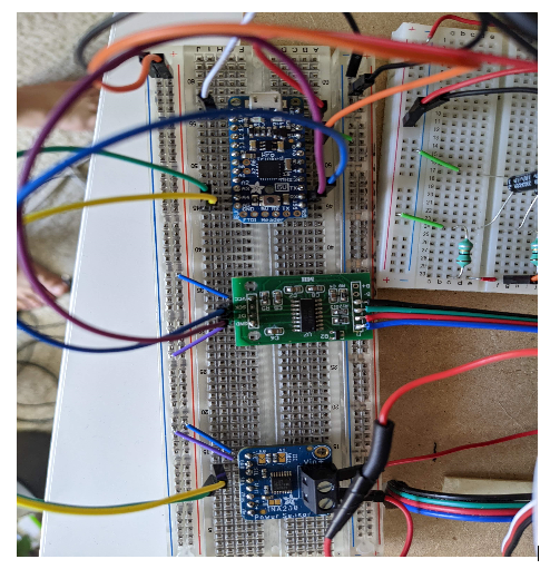
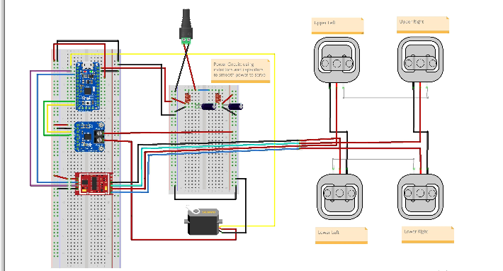
At this stage we will assemble the electronics on a breadboard to ensure that all of our electronic components are functioning as intended. Build the power circuit as shown in the diagram, but do not connect the yellow signal wire for the servos. The left side of the circuit is the power for the Arduino and the right side of the circuit is the power for the servos. Power to the servos also runs through an Adafruit INA260 current and voltage sensing chip which will act as our safety system. When you are satisfied that the voltages are correct when the components are powered, complete the wiring for the chips, making sure to connect the male and female RGB headers, this will connect your scale to the feeder.
Step 6: Coding and Testing
/**
Developed for Hobbyiest use by Tomas Diaz-Wahl for Kalliot LLC.
Copyright © 2022 Rocks LLC
Redistribution and use in source and binary forms, with or without modification, are permitted provided that the following
conditions are met:
1. Redistributions of source code and documentation must retain the above copyright notice, this list of conditions and the
following disclaimer.
2. Redistributions in binary form must reproduce the above copyright notice, this list of conditions and the following
disclaimer in the documentation and/or other materials provided with the distribution.
3. Neither the name of the copyright holder nor the names of its contributors may be used to endorse or promote products
derived from this software without specific prior written permission.
THIS SOFTWARE AND DOCUMENTATION ARE PROVIDED BY THE COPYRIGHT HOLDERS AND CONTRIBUTORS "AS IS" AND ANY EXPRESS OR IMPLIED WARRANTIES,
INCLUDING, BUT NOT LIMITED TO, THE IMPLIED WARRANTIES OF MERCHANTABILITY AND FITNESS FOR A PARTICULAR PURPOSE ARE
DISCLAIMED. IN NO EVENT SHALL THE COPYRIGHT HOLDER OR CONTRIBUTORS BE LIABLE FOR ANY DIRECT, INDIRECT, INCIDENTAL,
SPECIAL, EXEMPLARY, OR CONSEQUENTIAL DAMAGES (INCLUDING, BUT NOT LIMITED TO, PROCUREMENT OF SUBSTITUTE GOODS OR SERVICES;
LOSS OF USE, DATA, OR PROFITS; OR BUSINESS INTERRUPTION) HOWEVER CAUSED AND ON ANY THEORY OF LIABILITY, WHETHER IN CONTRACT,
STRICT LIABILITY, OR TORT (INCLUDING NEGLIGENCE OR OTHERWISE) ARISING IN ANY WAY OUT OF THE USE OF THIS SOFTWARE,
EVEN IF ADVISED OF THE POSSIBILITY OF SUCH DAMAGE.
**/
/*
* This project uses two third-party libraries.
* INA260 and HX711 libraries can be found at:
*
Adafruit_INA260 ina260 = Adafruit_INA260();
Servo servo;
HX711 scale;
/*
* Debug class is designed to output info to the serial monitor, (found under the tools menu in the Arduino IDE),
* This is designed to make sure that all boards and electronics are working as designed.
* TO ACTIVATE DEBUG CLASS MAKE SURE debugOn IS SET TO TRUE.
*/
class Debug {
public:
static const bool debugOn = false; //turn debug on and off
void printMsg(int x){
if (debugOn){
Serial.print(x);
Serial.flush();
}
}
void printMsg(String x){
if (debugOn){
Serial.print(x);
Serial.flush();
}
}
void printLine(int x){
if (debugOn){
Serial.println(x);
Serial.flush();
}
}
void printLine(String x){
if (debugOn){
Serial.println(x);
Serial.flush();
}
}
void setUpSerial(){
if (debugOn){
Serial.begin(9600);
// Wait until serial port is opened
while (!Serial) { delay(10); }
}
}
};//Debug
/*
* Queue class is designed to make a basic queue for our current measurements.
* There is no need to modify this class.
*/
class Queue{
private:
const static int maxQueueSize = 8;
float arr [maxQueueSize];
int queuePos;
public:
Queue(){
for (int i = 0; i < maxQueueSize; i++)
{
arr[i] = 0;
}
queuePos = maxQueueSize - 1;
}// Queue constructor
int enqueue (float val){
queuePos += 1;
if (queuePos >= maxQueueSize){
queuePos = 0;
}
arr[queuePos] = val;
}
float getAvg (){
float total = 0;
float avg;
for (int i = 0; i < maxQueueSize; i++){
total += arr [i];
}
avg = total / maxQueueSize;
return avg;
}
};// class Queue
/*
* Feeder class allows for motion of the feeder lid as well as implementing a check
* to see if there is an obstruction affecting lid motion.
* You will need to change several variable in the private data section of this class.
* You MUST change: calibrationFactor, minCatWeight, maxCatWeight
* You MAY need to change: maxCurrent, lidMaxPosition, any pin designations you wish to change.
*/
class Feeder {
public:
const int moveAmount = 1; // How much the servo should move per command
/*
* Set up stores an known initial position in the microcontroller memory.
* Tells the microcontroller which pin the servo is on.
* Activates and sets the scale calibration factor (see SparkFun_HX711_Calibration sketch)
*/
void setUp () {
servo.write (initialPos);
servo.attach(servoPin);
delay (1000);
scale.begin(LOADCELL_DOUT_PIN, LOADCELL_SCK_PIN);
scale.set_scale(calibrationFactor); //This value is obtained by using the SparkFun_HX711_Calibration sketch
}
/*
* reset should be called when powering up the feeder but can be called manually as well.
* reset tares the scale as well as moves the servo to a known position and then slowly moves the servo to position 0.
*/
void reset () {
scale.tare(); //Assuming there is no weight on the scale at start up, reset the scale to 0
servo.write (initialPos);
delay (500);
for (int i = initialPos; i > lidMinPosition; i--){
servo.write (i);
delay (servoDelay);
}
pos = lidMinPosition;
numberOfRetries = 0;
}
bool IsCatOn ()
{
float weight = scale.get_units();
return ((weight >= minCatWeight) && (weight <= maxCatWeight));
}
void moveServo (int amount){
pos += amount;
servo.write(pos);
}
void raiseLid (int amount){
moveServo(amount);
}
void lowerLid (int amount){
moveServo (-amount);
}
/*
* Open and close lid are nearly identical in function (haha! get it? they’re actually methods)
* These methods are designed to use the Adafruit INA260 current sensor to detect the current during operation.
* If the current draw from the servo is too high, it may indicate an obstruction.
* The implementation of this is a little complex so I recommend not messing with these values.
*/
float openLid () {
while ((pos < lidMaxPosition) && (numberOfRetries < maxRetriesAllowed))
{
raiseLid(moveAmount);
float current = ina260.readCurrent();
myQueue.enqueue(current);
if (myQueue.getAvg() >= maxCurrent){
numberOfRetries += 1;
lowerLid(5);
delay(1000);//Wait before lid open retry
debug.printLine("Max Current Detected, Closing Lid Before Retry");
if(numberOfRetries > maxRetriesAllowed){
exit (-1);//Lid is blocked
}
closeLid();
return;
}
delay(servoDelay);
} // end while loop
numberOfRetries = 0;//reset counter
} // openLid
void closeLid (){
while (pos > lidMinPosition)
{
lowerLid(moveAmount);
float current = ina260.readCurrent();
myQueue.enqueue(current);
if (myQueue.getAvg() >= maxCurrent){
numberOfRetries += 1;
raiseLid(5);
delay(1000);
debug.printLine("Max Current Detected, Opening Lid Before Retry");
if(numberOfRetries > maxRetriesAllowed){
exit (-1);//Lid is blocked
}
openLid();
return;
}
delay(servoDelay);
} // end while loop
numberOfRetries = 0; //reset retry counter
} // CloseLid
private:
const float calibrationFactor = -9660.0; //This value is obtained using the SparkFun_HX711_Calibration sketch.
const int LOADCELL_DOUT_PIN = 10;
const int LOADCELL_SCK_PIN = 11;
const int servoDelay = 40; // Speed of servo. (change not recommended)
const int initialPos = 20; // initial position of servo when feeder is reset. Be careful!; servo will move at max speed to this position.
const int lidMaxPosition = 70; // Maximum position of servo may vary depending on tolerances.
const int lidMinPosition = 0;
const int servoPin = 9;
const float minCatWeight = 11.0; // lbs. Set the minimum activation weight of your animal.
const float maxCatWeight = 1000.0; // lbs. Set the maximum weight of animal. (if you have a bigger dog or cat you dont want getting into the feeder)
const float maxCurrent = 250.00; // Maximum current that is allowed under normal feed operation. Triggers overcurrent protection mechanism.
const int maxRetriesAllowed = 10; // Maximum number of lid movement commands during overcurrent protection before lid operation ceases.
const int numberOfMeasurements = 5; // Number of current measurements to be averaged.
int pos;
int numberOfRetries;
Queue myQueue;
Debug debug;
}; // Feeder
Feeder feeder;
Debug debug;
void setup() {
delay(1000); //wait for boot up
// DEBUG BEGIN
debug.setUpSerial(); // Enables serial port communication. (Make sure debugOn set to true in debug class for USB serial communication)
debug.printLine("Adafruit INA260 Test");
if (!ina260.begin()) {
debug.printLine("Couldn’t find INA260 chip");
exit (-1);
}
debug.printLine("Found INA260 chip");
debug.printLine("Configuring Ina");
debug.printMsg("INA260_TIME_8_244_ms = ");
debug.printLine(INA260_TIME_8_244_ms);
ina260.setCurrentConversionTime(INA260_TIME_8_244_ms); // Changes the measurement interval. This makes current readings less spikey.
debug.printMsg("INA260_COUNT_4 = ");
debug.printLine(INA260_COUNT_4);
ina260.setAveragingCount(INA260_COUNT_4); // Changes the number of measurements averaged by the INA260 sensor. This will also make readings less spikey.
INA260_ConversionTime convTime = ina260.getCurrentConversionTime(); // Verifying Ina Configuration
INA260_AveragingCount avgCount = ina260.getAveragingCount(); // Verifying Ina Configuration
if (convTime != INA260_TIME_8_244_ms){
exit(-1);
}
if (avgCount != INA260_COUNT_4){
exit(-1);
}
debug.printLine("Configured Ina");
// DEBUG END
feeder.setUp(); // initialize feeder.
feeder.reset(); // set feeder lid to position 0 and tare scale.
delay(2000);// During construction of the feeder, this delay can be set much higher to align the servo gear with the door gear. (avoid pinchy fingies)
}
void loop() {
debug.printLine("I’m in the loop");
// The following code was used during construction for debug purposes
// feeder.openLid();
// feeder.closeLid();
//debug.printLine("Program Exit");
//
// exit(0);
//END DEBUG
//main code for feeder operation
if (feeder.IsCatOn()) {
feeder.openLid();
}
else{ // Cat is not on the feeder
feeder.closeLid();
}
delay(1000);
}
Now that everything is connected, you can move on to applying the code. Power on the circuit by plugging in the power supply. Connect your Arduino or Pro Trinket to your computer using the USB cable. Always make sure to power your circuit when connected to the computer, otherwise the servo may try to draw power through the signal line, which could damage our component. You may want to temporarily disconnect the signal line of the servo. Copy the provided code into a new sketch in the Arduino IDE and save it. Make sure to add the INA260 library to the IDE. The Servo library should be included by default, and you should have added the HX711 library when you calibrated the scale. All three libraries need to be included for this project.
1) Turn on debug mode by going to the debug class and setting debugOn to true.
2) Go into the Feeder class and go into the Private Data section at the bottom.
3) Change the calibrationFactor to the value you obtained in the scale calibration step, making sure to add one decimal place.
4) Change minCatWeight to be slightly less than your pet's weight.
5) Do not change maxCatWeight yet.
6) If you are using different pin names than those in the wiring diagram, you can set them in this section.
7) Compile and upload the sketch to your Arduino.
8) Open the serial monitor in the Arduino IDE and make sure the INA260 chip is found.
9) It should then print "I'm in a loop" over and over again.
10) Return to the debug class and set debugOn to false.
11) Connect the signal cables from the servos and re-upload the sketch.
12) The servo should rotate to 20 degrees and then slowly rotate back to zero.
13) Disconnect USB and power.
14) We now know the position of the servo at zero. Align the miter gears of the servo and shaft and add the four fasteners to the corners, being careful not to snag any of the wires. The cover should close completely with no play.
15) Reconnect power to the feeder. The cap should quickly rise to 20 degrees and then slowly approach zero. This is the calibration phase and will occur every time the feeder is powered.
16) Put some weight on the scale and watch it open.
17) Make sure it is closed when you remove the weight.
18) You can test the safety feature by preventing the cover from moving. (If the safety feature fails, use caution)
If your feeder is working properly, it's time to move on to the final steps.
Mount the completed feeder to the scale using double-sided tape or Velcro.
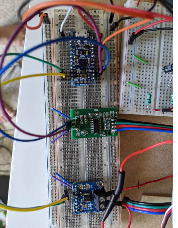
Set maxCatWeight to something slightly larger than your pet's weight and re-upload the sketch, but this time with your Pro Trinket. Make sure everything is ok on the breadboard. We will minimize the size of the electronics by moving everything to the solder pads. Using the same wiring diagram as before Figure 4, add each component to the soldering board. The exact arrangement of the components does not matter, as long as the connections are the same as in the wiring diagram. You can copy the arrangement in Figure 10. Figure 11 shows how to bridge the connections with solder.
Mount the pads to the electronics holder and secure them inside the feeder using double sided tape or Velcro.
In order to not install the shroud covering the gears, the cover must be completely open. Slide the cover into place and close the cover. Place the set screw at the top to secure the shroud in place.
We plugged the feeder into a Govee smart plug so we could control it using a smart speaker.
- Share a solar beacon circuit
- How to convert digital values into analog values by connecting MCP4725 with Arduino
- Make a draft beer machine using Windows 10 UWP
- DIY an open source air quality monitor
- How to build an autonomous robot using the DonkeyCar platform
- Analysis of the circuit principle of ZX5-630 welding machine
- Homemade video switcher
- A detection circuit with keen hearing
- Analysis of the circuit of DL-01 low-frequency electrotherapy instrument
- Electronic mosquito repellent circuit diagram
- Have you learned about STMicroelectronics’ NFC technology?
- Based on NFC universal card reader circuit diagram
- Design of universal card reader circuit based on NFC
- How does an optocoupler work? Introduction to the working principle and function of optocoupler
- 8050 transistor pin diagram and functions
- What is the circuit diagram of a TV power supply and how to repair it?
- Analyze common refrigerator control circuit diagrams and easily understand the working principle of refrigerators
- Hemisphere induction cooker circuit diagram, what you want is here
- Circuit design of mobile phone anti-theft alarm system using C8051F330 - alarm circuit diagram | alarm circuit diagram
- Humidity controller circuit design using NAND gate CD4011-humidity sensitive circuit


 京公网安备 11010802033920号