How to use CAN protocol in Arduino
Source: InternetPublisher:D先生 Keywords: CAN MCP2515 Arduino Updated: 2024/12/27
Any average car today contains around 60 to 100 sensor units for sensing and exchanging information. This number will only get higher as car manufacturers continue to make their cars smarter with features like autonomous driving, airbag systems, tire pressure monitoring, cruise control systems, etc. Unlike other sensors, these sensors process critical information, so the data from these sensors should be communicated using standard automotive communication protocols. For example, cruise control system data like speed, throttle position, etc. are important values sent to the Electronic Control Unit (ECU) in order to decide the acceleration level of the car, and miscommunication or data loss here can lead to serious malfunctions. Therefore, instead of standard communication protocols like UART, SPI, or I2C, designers use more reliable automotive communication protocols like LIN, CAN, FlexRay, etc.
In this article, we will go over the basics again and we will also end up exchanging data between two Arduinos using CAN communication.
Introduction to CAN
CAN aka Controller Area Network is a serial communication bus designed for industrial and automotive applications. It is a message-based protocol used for communication between multiple devices. When multiple CAN devices are connected together as shown in the figure below, the connection forms a network, just like our central nervous system, allowing any device to talk to any other device in the node.

A CAN network will consist of only two wires, CAN High and CAN Low, for bidirectional data transmission as shown above. Typically, CAN communication speeds range from 50 Kbps to 1Mbps, and the distance range can range from 40 meters at 1Mbps to 1000 meters at 50kpbs.
CAN message format:
In CAN communication, data is transmitted in the network in a specific message format. This message format contains many segments, but the two main segments are the identifier and the data that helps in sending and responding to messages in the CAN bus.
Identifier or CAN ID: The identifier is also called CAN ID or also PGN (Parameter Group Number). It is used to identify a CAN device present in a CAN network. Depending on the type of CAN protocol used, the length of the identifier is 11 or 29 bits.
Standard CAN: 0-2047 (11 bits)
Extended CAN: 0-2 29 -1 (29 bits)
Data: This is the actual sensor/control data that must be sent from one device to another. Size The data can be from 0 to 8 bytes long.
Data Length Code (DLC): 0 to 8 Indicates the number of data bytes present.
Wires used in CAN:
The CAN protocol consists of two wires, CAN_H and CAN_L, for sending and receiving information. Both wires act as differential lines, which means that the CAN signal (0 or 1) is represented by the potential difference between CAN_L and CAN_H. If the difference is positive and greater than a certain minimum voltage, it is 1, and if the difference is negative, it is 0.
CAN communication is usually done using twisted pair cables. As shown in the figure, a 120 ohm resistor is usually used at both ends of the CAN network because the lines need to be balanced and connected to the same potential.
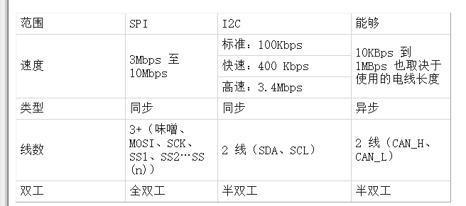
Comparison between CAN over SPI and I2C
Now that we have learned how to use SPI with Arduino and IIC with Arduino, let's compare the characteristics of SPI with I2C and CAN
CAN protocol applications
Due to the robustness and reliability of CAN protocols, they are used in industries such as automobiles, industrial machinery, agriculture, medical equipment, etc.
Due to the reduced wiring complexity in CAN, they are mainly used in automotive applications such as cars.
The implementation cost is low and the hardware components are also inexpensive.
Easy to add and remove CAN bus devices.
How to use CAN protocol in Arduino
Since Arduino does not contain any in-built CAN port, a CAN module called MCP2515 is used. This CAN module is interfaced with Arduino via SPI communication. Let us learn more about MCP2515 and how it interfaces with Arduino.
MCP2515 CAN Module:
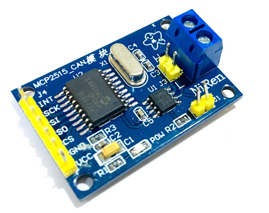
The MCP2515 module has a CAN controller MCP2515, which is a high-speed CAN transceiver. The MCP2515 is connected to the MCU via SPI. Therefore, it is easy to connect to any microcontroller with an SPI interface.
For beginners who want to learn CAN Bus, this module will be a good start. This CAN SPI board is perfect for industrial automation, home automation, and other automotive embedded projects.
Features and specifications of the MCP2515:
Using high-speed CAN transceiver TJA1050
Size: 40×28mm
SPI control for expanding multiple CAN bus interfaces
8MHZ crystal oscillator
120Ω terminal resistor
With independent buttons, LED indicator light, power indicator light
Supports 1 Mb/s CAN operation
Low current standby operation
Up to 112 nodes can be connected
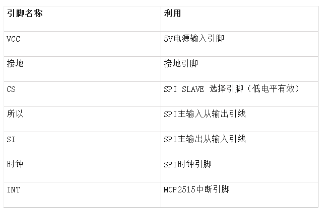
Pinout of the MCP2515 CAN module:
In this tutorial, let us see how to send Humidity and Temperature (DHT11) sensor data from Arduino Nano to Arduino Uno through CAN bus module MCP2515.
Required Components
Arduino UNO
Arduino Nano
DHT11
16x2 LCD display
MCP2515 CAN Module – 2
10k Potentiometer
Breadboard
Connect the wires
MCP2515 Arduino Circuit Diagram
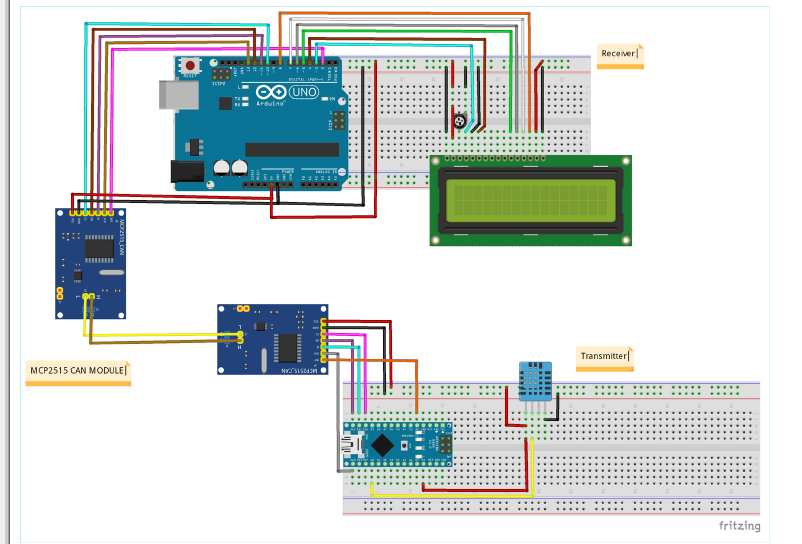
CAN Transmitter connection:
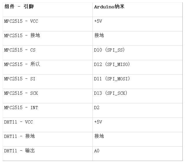
Circuit connection on the CAN receiver side:
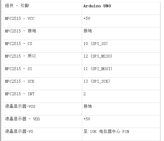
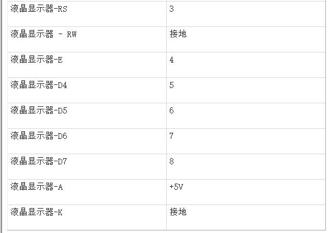
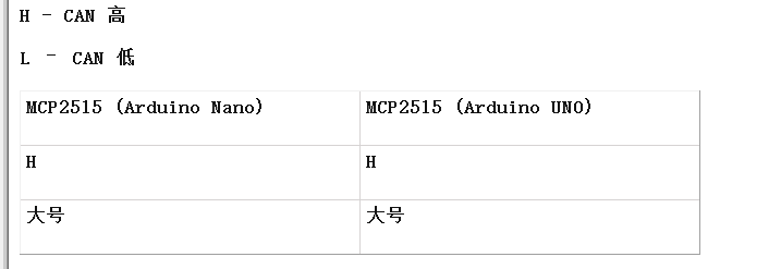
Connection between two MCP2515 CAN modules
After making all the connections, my hardware looks like this:
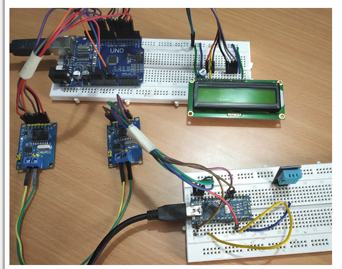
Programming Arduino for CAN Communication
First, we have to install the CAN library in Arduino IDE. By using the following library, interfacing MCP2515 CAN module with Arduino becomes easier.
In this tutorial, the coding is divided into two parts, one is the CAN Transmitter Code (Arduino Nano) and the other is the CAN Receiver Code (Arduino UNO), both can be found at the bottom of this page. The instructions are as follows.
Before writing a program to send and receive data, please make sure you have installed the library as described above and the CAN module MCP2515 is initialized in your program as follows.
Initialize the MCP2515 CAN module:
To create a connection to the MCP2515, follow these steps:
1. Set the pin number of the SPI CS connection (default 10)
MCP2515 mcp2515(10);
2. Set the baud rate and oscillator frequency
mcp2515.setBitrate(CAN_125KBPS, MCP_8MHZ);
Available baud rates:
CAN_5KBPS, CAN_10KBPS, CAN_20KBPS, CAN_31K25BPS, CAN_33KBPS, CAN_40KBPS, CAN_50KBPS, CAN_80KBPS, CAN _83K3BPS, CAN_95KBPS, CAN_100KBPS, CAN_125KBPS, CAN_200KBPS, CAN_250KBPS, CAN_500KBPS, CAN_1000KBPS.
Available clock speeds:
MCP_20MHZ, MCP_16MHZ, MCP_8MHZ
3. Set the mode.
mcp2515.setNormalMode();
mcp2515.setLoopb
CAN Transmitter Code Description (Arduino Nano)
In the transmitter part, Arduino Nano interfaces with MCP2515 CAN module through SPI pins and DHT11 sends the temperature and humidity data to the CAN bus.
First include the required libraries, SPI library for communication using SPI, MCP2515 library for communication using CAN and DHT library for using DHT sensor with Arduino. We have previously interfaced DHT11 with Arduino.
#include
Now define the pin name of DHT11 (OUT pin) connected to A0 of Arduino Nano
#define DHT
Also, DHTTYPE is defined as DHT11.
#define DHTTYPE DHT11
The canMsg structure data type is used to store the CAN message format.
struct can_frame canMsg;
Set the pin number for the SPI CS connection (default is 10)
MCP2515 mcp2515(10);
Furthermore, an object of DHT class dht is initialized with the DHT pin of Arduino Nano and DHT type as DHT11.
DHT dht(DHTPIN, DHTTYPE);
Next in void setup():
Use the following statement to start SPI communication
SPI.begin();
Then use the following statements to start receiving temperature and humidity values from the DHT11 sensor.
dht.begin();
Next, reset the MCP2515 using the following command
mcp2515.reset();
Now the speed of MCP2515 is set to 500KBPS and 8MHZ as the clock
mcp2515.setBitrate(CAN_500KBPS,MCP_8MHZ);
And the MCP2525 is set to normal mode
mcp2515.setNormalMode();
In the void loop():
The following statement gets the humidity and temperature values and stores them in integer variables h and t.
int h = dht.re
Next, the CAN ID is 0x036 (as per selection), the DLC is 8, we assign the h and t data to data[0] and data[1], and leave all data as 0.
canMsg.can_id = 0x036;
canMsg.can_dlc = 8;
canMsg.data[0] = h; //Update the humidity value in [0]
canMsg.data[1] = t; //Update the temperature value in [1]
canMsg.data[2] = 0x00; //All 0s are used for rest
canMsg.data[3] = 0x00;
canMsg.data[4] = 0x00;
canMsg.data[5] = 0x00;
canMsg.data[6] = 0x00;
canMsg.data[7] = 0x00;
After all, to send a message to the CAN BUS, we use the following statement.
mcp2515.sendMessage(&canMsg);
So now the temperature and humidity data are sent as messages to the CAN bus.
CAN Receiver Code Description (Arduino UNO)
In the receiver section, Arduino UNO is interfaced with MCP2515 and 16x2 LCD display. Here, Arduino UNO receives the temperature and humidity from the CAN bus and displays the received data in the LCD.
First include the required libraries, SPI library for using SPI communication, MCP2515 library for using CAN communication and LiquidCrsytal library for using 16x2 LCD with Arduino.
#include
Next, define the LCD pins for connecting to Arduino UNO.
const int rs = 3, en = 4, d4 = 5, d5 = 6, d6 = 7, d7 = 8;
LiquidCrystal lcd(rs, en, d4, d5, d6, d7);
A structure data type is declared to store the CAN message format.
struct can_frame canMsg;
Set the pin number for the SPI CS connection (default is 10)
MCP2515 mcp2515(10);
In void setup():
First set the LCD to 16x2 mode and display a welcome message.
  lcd.start(16,2);
lcd.setCursor(0,0);
  lcd.print("Circuit Abstract");
  lcd.setCursor(0,1);
  lcd.print("CAN ARDUINO");
  delay(3000);
  lcd.clear();
Use the following statement to start SPI communication.
SPI.begin();
Next, reset the MCP2515 using the following command.
mcp2515.reset();
Now set the MCP2515 to 500KBPS speed and 8MHZ as clock.
mcp2515.setBitrate(CAN_500KBPS,MCP_8MHZ);
The MCP2525 is set to Normal mode.
mcp2515.setNormalMode();
Next in void loop():
The following statement is used to receive a message from the CAN bus. If a message is received, it enters the if condition.
if (mcp2515.readMessage(&canMsg) == MCP2515::ERROR_OK)
In the if condition, data is received and stored in canMsg, data[0] with the humidity value and data[1] with the temperature value. Both values are stored in integers x and y.
 int x = canMsg.data[0];
     int y = canMsg.data[1];
After receiving the values, the temperature and humidity values are displayed on the 16x2 LCD display using the following statements.
 lcd.setCursor(0,0);
lcd.print("Humidity:");
lcd.print(x);
lcd.setCursor(0,1);
      lcd.print("Temperature:");
      lcd.print(y);
      delay(1000);
      lcd.clear();
Working of CAN Communication in Arduino
Once the hardware is ready, upload the programs for the CAN transmitter and CAN receiver (full programs are given below) to their respective Arduino boards. After powering on, you should notice that the temperature value read by the DHT11 will be sent to the other Arduino via CAN communication and displayed on the LCD of the second Arduino as shown in the following figure. I also used an AC remote control to check if the temperature displayed on the LCD is close to the actual room temperature.
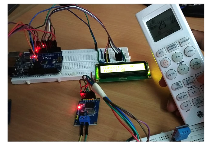
CAN Transmitter Code (Arduino Nano):
#include
- Share the features of Wi-Fi 6 that you don’t know
- Production of a FM wireless microphone
- Convenient and practical multifunctional wireless nursing assistance device
- Design and Analysis of Half-duplex Intercom Circuit Using LM386
- RXM-900-HP-II FM/FSK 928~902 MHz Receiver Module
- nRF401/nRF403433/315 MHz Transceiver
- MC33493/D OOK/FSK 928~902 MHz/434~315 MHz dual frequency transmitter
- RXM-433/418/315-LC-P AM Receiver Module
- RF2516 AM/ASK/OOK 433/315 MHz Transmitter
- MICRF500 FSK 1000~700 MHz Transceiver
- USB communication circuit
- Indoor unit communication circuit
- Two-way communication circuit circuit diagram
- Long distance serial communication circuit
- CAN bus communication circuit
- Wireless transmitter circuit diagram
- Time division multiplexing stereo decoder circuit
- Design of wireless transmitting and receiving circuit based on Bluetooth
- Fiber optic transceiver circuit diagram
- Square wave generation circuit


 京公网安备 11010802033920号