Design of an autonomous plant watering system using ATtiny85
Source: InternetPublisher:jikai233 Keywords: Humidity sensor watering device Updated: 2024/12/31
Do you want to implement one of the following functions:
Received a warning (siren, text message, etc.) and went to water the plants?
After a period of time (usually a few days), the timing machine will pour some water. Maybe your plant doesn't do this at that time!
Relying solely on the humidity sensor. Big mistake! The local humidity can mislead the average humidity of the pot!
Your device is monitoring the plants, watering them when needed. You just have to access it from time to time and refill the water container when needed.
The last option was chosen in this project.
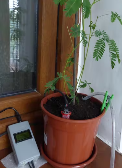
This is the central unit that displays the mimosa emoji: Happy:) Normal:| or Unsatisfied:( , followed by the soil moisture (%), the number of days and hours since the last watering. You can use any other display, of course. This display was reused from another board (Pololu A-Star Prime).


Humidity Sensor
It's a resistivity based sensor and won't corrode. If you only turn the power on for a few milliseconds at a time , just long enough to read the humidity, it will work fine. The one I showed you has worked for years with no signs of corrosion. Just use the included software.
But other problems may occur: wet mud clings to the sensor and therefore indicates a different local humidity than the rest! Also if the sensor is too far from the water pipe, there will be a big delay in the reading: it takes the time it takes for the water to diffuse in the pot. Put it closer to the water pipe to stop pumping water so that there is not too much moisture. Change the humidity threshold in the software according to your plant requirements. This pumps water below 95% humidity (after some tests with my mimosa I changed this threshold to 75%) for a certain number of seconds, depending on the size of the pot. Then, after the reading time (10-15 minutes), if the indicated humidity has not exceeded the threshold, a new amount of water is pumped, but with a limited number of iterations.
This method allows time for the water to diffuse in the pot. Allow watering only twice in a given time interval (8-12 hours) to avoid watering before diffusion and some possible temporary errors of the sensor. It is recommended to recalibrate the humidity sensor every few months: adjust the thresholds in the software: the value of the sensor in the air (0% humidity) and the value of the sensor short circuit (100% humidity).
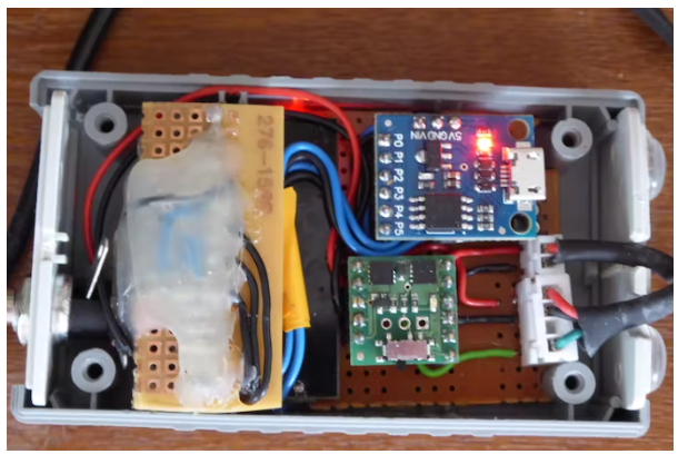
As microcontroller we recommend using the At Tiny85: it has the necessary IO pins, just enough, and is cheaper than other microcontrollers.
The whole unit (including the pump) is continuously powered by a 220V power adapter, providing 9V/0.5A. In the event of a power failure (hopefully it won't last more than a few days, otherwise the plants will dry out!), this is not a problem. If necessary, the system will restart, read the humidity and pump water, then will reset the hour and day counters.
Powering the pump is done by a Mosfet module, but it can also be done by other means (such as relays). The display can be any other display with an I2C interface. This one has a parallel interface, so an I2C adapter is needed.
After one year of use
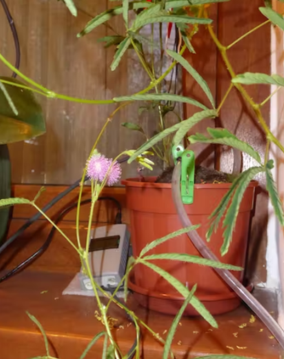
The project ran for more than 18 months. At one point, the humidity sensor stopped working. Fortunately, there was no environmental demand for humidity during this period and the software pumped water every 2 days. Now it has been replaced and everything is working fine.
NOTE: New moisture thresholds from 95% to 75% must be tested and set in code! Variability of product and soil salinity!


Arduino code for Attiny-plant-care:
/* Sketch for ATtiny85. Based on the Digispark (Use Digispark Default 16.5 MHz), no port select.
* Compile, Upload and then coonect ATtiny85 to USB.
* {ATtiny85 alone pins: 1=PB5, 2=PB3,ADC3, 3=PB4,ADC2, 4=GND, 5=PB0,MOSI,SDA, 6=PB1,MISO, 7=PB2,SCK,SCL, 8=VCC}
* ATtiny Pin 5 = PB0 (P0 on ATTiny board) = SDA
* ATtiny Pin 7 = PB2 (P2 on ATTiny board) = SCK=SCL
* ATtiny PB1 = to SWITCH power of a POLOLU MOSFET: power the Pump (6-12V)
* ATtiny PB3 = Humidity sensor output= analog read
* ATtiny PB4 = Power for the sensor (pin: 20mA = sufficient)
* Uses 26 mA for CPU, Sensor + Mosfet on + Display
* Uses 20 mA for CPU + Display (between readings)
* Uses 8 mA in deep sleep (Display on only)
* Between reads: deep sleep. Protection against over-watering by humidity sensor.
*/
#include
#define LED_BUILTIN PB5 // Change PB5 to PB1 only for testing delays
#define powsen PB4 // PB4 provides 4.1V to power the humidity sensor
#define sensor PB3 // Sensor data pin for analog read
#define pump PB1 // Pin for LED & MOSFET feeding the Pump
// Reading humidity once in 30min...1hour is sufficient:
int D, H, nr=100; // Attiny85 will sleep nr*9 (sec.) (E.g. 200=>30min; 400=>1h))
unsigned long psec, corr=nr*300; // time counter since start or watering
//This runs each time the watch dog wakes us up from sleep
ISR(WDT_vect) {
//Don’t do anything. This is just here for wake up.
}
void setup() {
lcd.init(); lcd.backlight(); lcd.clear();
pinMode(powsen,OUTPUT); // Power to the sensor by powsen PIN
pinMode(sensor, INPUT); // Sensor read value from sensor PIN
pinMode(pump, OUTPUT); // Pump control PIN
pinMode(LED_BUILTIN, OUTPUT);
set_sleep_mode(SLEEP_MODE_PWR_DOWN); // sleep mode is set here
sleep_enable(); // enables the sleep bit in the mcucr register, so sleep is possible
psec=0; // Starting moment
}
void loop() {
adc_enable();
digitalWrite(LED_BUILTIN, HIGH); // turn the LED on (HIGH is the voltage level)
digitalWrite(powsen,HIGH); // Power on the sensor
int humidity=analogRead(sensor); // Read sensor data
delay(200); // A short time, just to read the sensor!
digitalWrite(powsen,LOW); // Power off the humidity sensor
digitalWrite(LED_BUILTIN, LOW); // turn the LED off by making the voltage LOW
// Convert analog values from sensor to humidity. Tested: free and short-circuit.
humidity = constrain(humidity, 85, 660); // accept values between these limits for 4.8V on sensor
humidity = map(humidity, 85, 660, 0, 100); // and map them between 0 and 100%
// The pump is started if humidity drops below a level determined for each plant!
// Then, the pump cannot restart before ’pause’, waiting for water to diffuse in the pot.
// Set below the DRY Limit for Your Plant (E.G.: 95):
if (humidity<=95) {
digitalWrite(pump,HIGH); // Power the pump through a Pololu-LV-MOSFET
delay(15000); // Time [ms] to pump the tested REQUIRED volume of WATER to the plant!!
digitalWrite(pump,LOW); // Power down the pump through the MOSFET
delay(1000);
psec=0; // Reset timer of water pumping.
// Test that after [nr*9] seconds (15min in this case), water was absorbed and sensor is above threshold.
// Otherwise, the pump will start again after. Warning: too much water can be bad for your plant!
}
// Show the results on the screen
lcd.setCursor(0, 0); lcd.print("Mimosa:");
if (humidity>95)
if (humidity>97)
lcd.print(")");
else
lcd.print("|");
else
lcd.print("(");
lcd.setCursor(0, 1);
lcd.print(humidity); lcd.print("%"); // Write on LCD the humidity (%) and
D=psec/86400; // days since last watering/reset ...
H=(psec%86400)/3600; // and hours
lcd.print(D); lcd.print("d");
lcd.print(H); lcd.print("h ");
// Most of the time, go to sleep for ’nr’ multiples of 8 seconds + opp. time
adc_disable(); // ADC uses ~320uA
for (int i=0; i
// ===================================================================
void setup_watchdog(int timerPrescaler) {
//Sets the watchdog timer to wake up, but not reset
//0=16ms, 1=32ms, 2=64ms, 3=128ms, 4=250ms, 5=500ms
//6=1sec, 7=2sec, 8=4sec, 9=8sec
//From: http://interface.khm.de/index.php/lab/experiments/sleep_watchdog_battery/
if (timerPrescaler > 9 ) timerPrescaler = 9; //Limit incoming amount to legal settings
byte bb = timerPrescaler & 7;
if (timerPrescaler > 7) bb |= (1<<5); //Set the special 5th bit if necessary
//This order of commands is important and cannot be combined
MCUSR &= ~(1<
- How to choose the right level of integration to meet motor design requirements?
- Model rocket launch controller circuit
- Controlling LEDs with Multithreading via Dual-Core Programming on Raspberry Pi using MicroPython
- Perform surgery on the speaker protection circuit
- Starting method of asynchronous motor with external frequency-sensitive resistor
- Design and analysis of wire control circuit
- Hydraulic control circuit design and analysis
- A novel and practical power line anti-theft and cutting alarm circuit
- Homemade short circuit alarm device
- Simple disconnection burglar alarm
- Chicken farm photoelectric control circuit
- Three-phase stepper motor control circuit
- Digital current loop control circuit
- Photoelectric output control circuit
- Detection and control circuit of electromagnetic stove
- Micro DC motor steady speed control circuit a
- audio signal control circuit
- Button type electronic volume control circuit
- Basic structure of power factor control circuit
- Apply LOGO! Electric gate control circuit b


 京公网安备 11010802033920号