Model rocket launch controller circuit
Source: InternetPublisher:武林萌主 Keywords: Controller controller circuit Updated: 2025/01/14
Model rockets are fun things to play with but can be dangerous if not handled with care. This rocket countdown launch controller is very useful when launching model rockets and also provides safety to the user. This launch controller circuit also has a counter that counts down from 0 to 7 via a 9-segment display during launch.
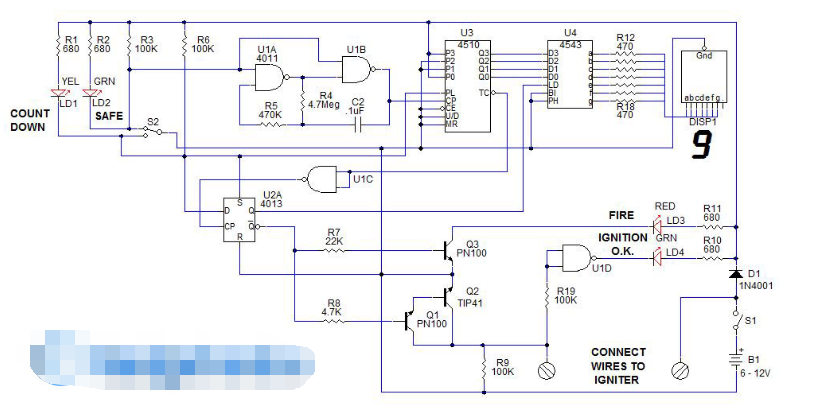
Model rocket launch controller circuit:

The controller is connected to the igniter via a two-conductor cable (at least 50 feet, the longer the better). The cable connects to the controller terminals. It connects to the igniter which is plugged into the rocket motor. The end of the ignition cable has two alligator clips for grabbing the two igniter leads.
This circuit has a feature that tells you that the igniter is wired correctly and that there is continuity through the igniter circuit. If everything is wired correctly, the ignition OK LED, LD1 (green), will illuminate when switch S4 (main power) is turned on. There are three LEDs that indicate the status of the controller. LED LD2 (green) indicates when switch S2 is in the "safe" position. LD1 (yellow) indicates when push button switch S2 is in the "countdown" position (pressed and held). LD3 (red) illuminates when the countdown reaches 0 and the model rocket launches.
Referring to the schematic, the circuit blocks will be described. U1A, U1B (CD4011 Quad 2-input NAND gates) form a 1Hz oscillator clock that runs a countdown. When S2 is in the "safe" position, the U1A, U1B inputs are grounded, disabling the clock. Additionally, U2A (CD4013, dual D, flip-flop) is set via R8, resulting in Q = 1, Qnot = 0. When Qnot = 0, transistors Q1, Q2, and Q3 are off. Q1 and Q2 form a Darlington pair that sinks current through the igniter to launch the rocket.
Q3 acts as a display buffer, turning on the "FIRE" LED when the firing sequence reaches zero.
The countdown counter consists of two IC’s U3 (CD4510, 4-bit U/D counter with preset), when S2 is in the “SAFE” position, when the PL (preset load) pin is high, P0 –
P3 (connected binary <>) is loaded into the counter. CEnot (chip enable low), MR (master reset), and U/D pins are connected to ground, enabling the chip, disabling the master reset, and causing the counter to count down.
The binary outputs of U3 are connected to Q3 – Q4 of U0 (CD4543 binary to 7-segment decoder, phase inverted). U4 takes the binary outputs of U3 and lights the corresponding segments of the 7-segment display. The common cathode of DSP1 is connected to ground. If you wish to use a common anode, 7-segment display, connect the common anode pin of the display and the PH (phase) pin of U4 to +V. This inverts the output polarity of the CD4543 decoder.
Boot sequence:
To better understand the operation, let's go through the firing sequence and explain what the circuit does. We connect the igniter via the ignition cable to the terminals of the firing controller. With the igniter on the terminals, the input to U1D is high. This causes the LD4, Ignition OK LED to illuminate. S2 is in the "safe" position so the LED, LD2 "safe" illuminates. The U1A, U1B clocks are stopped and the U3 counter is loaded with 9 and ready to count down. Setting U2A (Q = 1, Qnot = 0) enables U4 to update and decode any number presented in the Q0 – Q3 inputs. U2A, Qnot =
0, make sure the ignition circuit is off.
When S2 is pressed, the inputs of U1A, U1B go high, which allows the clock to output a pulse once per second. The PL (preset load) pin of U3 is low, allowing U3 to count down. U4 decodes the output of U3 and updates the countdown display DSP1. Pressing S2 also pulls the SET input low to U2A, allowing data to be clocked in. As a safety feature, when S2 is in the "SAFE" position, the "D" input of U2A is high. This prevents any stray noise from possibly getting an unwanted output condition from U2A. The D (data) pin of U2A remains low while S2 is in the countdown position.
When U3 reaches 0, U3's TCnot (borrow/carry) pin goes low. U1C inverts the signal and presents it to U2A's CP (clock pin). The D flip-flop switches its output, Q = 0, Qnot = 1. When this happens, the Q output freezes the display by taking U4's LD (load) pin low. Qnot = 1, turning on the Q1, Q2 Darlington pair and providing power to the igniter to launch the rocket. Q3 turns on LED LD3 to indicate that the ignition point has been reached.
When S2 is released after the rocket has been launched, U2A is reset, the clock is reset, the counter is preset to nine, and the "Countdown" LED turns off and the "Safety" LED turns on. The Ignition OK LED should turn off, indicating an open circuit. When setting up the next launch, S1 should be closed to save battery and ensure that no possible power source is available to the launch controller and igniter. Have fun, but be safe. This model rocket launch controller can help you do that.
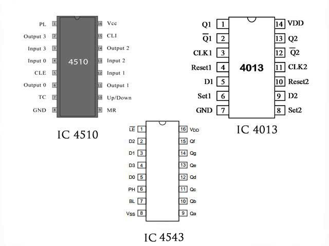
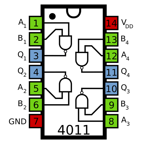
Integrated circuit pin diagram:


- How to remotely control devices using ESP8266 and LPC2148
- How can we make the robot move precisely on a predefined path?
- How to set up a cheap beam break sensor control distance scene using a reflector
- DC motor drive circuit composed of L293D
- JDB-LQ-TQ/2 motor full voltage starting circuit
- Starting method of asynchronous motor with external frequency-sensitive resistor
- A novel and practical power line anti-theft and cutting alarm circuit
- Homemade short circuit alarm device
- Precious home appliance anti-theft alarm
- Car audio system anti-theft circuit
- 26kW AC three-speed cargo crane control circuit
- Photoelectric controller circuit with anti-interference capability
- Chandelier brightness controller circuit three
- Newspaper column timing light controller circuit (1)
- Thyristor zero-crossing switch temperature controller circuit
- Electric mixer intermittent operation controller circuit
- Charging circuit diagram using LM3914 as controller
- stair lighting controller
- Electric fan multi-purpose controller
- Multi-variable flow light controller


 京公网安备 11010802033920号