How to build a light source that adjusts its brightness based on atmospheric conditions
Source: InternetPublisher:JFET Keywords: PWM IC555 LDR Updated: 2025/01/07
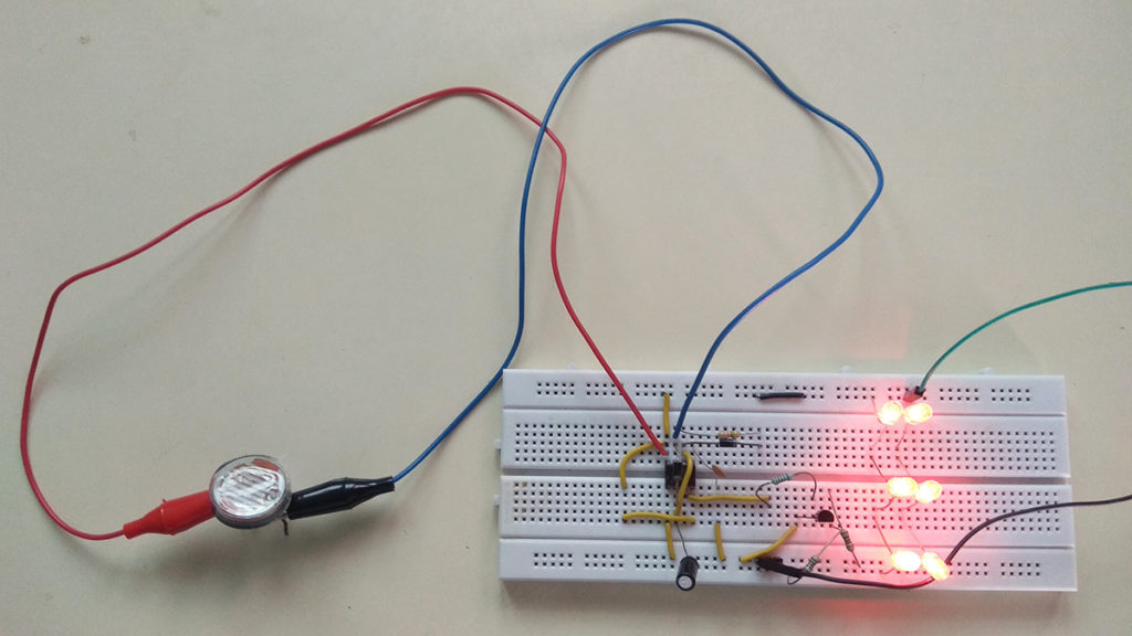
The timer IC555 is not dead yet, and this is because of the extended functionality it offers at a low cost. Whether it is an oscillator, timer, or trigger, this chip can do the job well. In this article, we will see how to build a light source that can adjust its brightness according to the atmospheric conditions. In other words, this LED beacon will light up brightly in the dark, while in daylight it will go off or produce minimal light.
This circuit uses the PWM function of IC 555. For those who don't know PWM is a technique of varying the off and on time of a pulse. This is mainly used to control the speed of motors, intensity of lights and to save power consumption.
In this circuit, we will use PWM to control the intensity of a light. To do this, we will generate a high frequency square wave and modify its mark and space ratio or on/off time. Increasing the on time of the pulses in this high frequency signal will increase the brightness of the light, while increasing the off time will decrease the brightness of our light.
Measure the resistance of the LDR:
Measure the resistance of the LDR under various lighting conditions. This is important to note because resistance varies greatly between different manufacturers. Therefore, I measured the resistance of the LDR under various lighting conditions (just a rough measurement to choose the capacitor and resistor values in the circuit) and noted them in the table below.

Keep in mind that, as mentioned before, the above table is meant to be roughly used for calibration. However, if you need to do this very accurately, you may want to use a light meter to measure the light intensity in lumens and then tabulate that with the corresponding LDR resistance. In my opinion, this project does not require a high level of accuracy, so I kept it simple.
Circuit working principle:

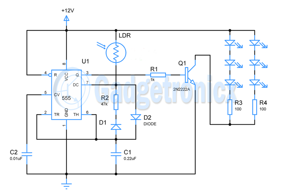
To understand the above circuit, it is best to read the working of “Timer IC 555”. In this circuit, this IC is connected as an astable multivibrator to generate a series of square wave pulses. The generation of this square wave pulse depends on the IC
The voltage in the two pins "Threshold/2nd Pin" and "Trigger/555th Pin" of 6. The output will remain high until the voltage in the threshold pin reaches +《》/《》 of the supplied VCC, and once the marked value is reached, the output will switch to low. The low state will remain until the voltage in the trigger pin drops below +《》/《》 of the supplied VCC.
As shown in the circuit above, these two pins are connected to the positive terminal of the capacitor. So, in a sense, the IC
The output state of the 555 depends on the voltage across the capacitor. When the system is turned on, capacitor C1 will start charging through the LDR and diode D1. As we all know, the resistance in the LDR decreases as the intensity of incident light increases. Therefore, during daytime or bright light conditions, the resistance of the LDR will be low, which in turn allows the capacitor to charge quickly to +《》/《》
Vcc.
Because diode D1 limits the current, resistor R2 does not play a role in charging the capacitor. Once the capacitor voltage reaches +2/3
Vcc flag, the output will switch to low which in turn activates the internal discharge transistor in pin 7. Now, the capacitor is discharged through resistor R1 and the voltage across the capacitor starts to drop. The low state in the output will remain until the capacitor voltage reaches +1/3 after it switches back to high.
Vcc. This turns off the discharge transistor and the whole cycle repeats.
Indicator Lights:

This part is very simple, the generated PWM signal is fed to the base of the transistor and drives the LED connected to its collector terminal. The transistor base will be activated by this PWM signal and the LED will be activated during the ON period of the signal. When driven by a higher frequency PWM signal, the LED is a slow component and will exhibit a continuous lighting or non-lighting effect as output. There you have your light response
LED Beacon. The LEDs will draw about 60mA. You can increase the number of LEDs to make a more powerful LED beacon.
calculate:
Here is a brief explanation about the calculations behind this circuit. We need to fix the values of R1 and C1 because the values of these components determine the frequency and off time of the PWM pulses in the output. We need a high frequency pulse to avoid flickering in the output. The smaller the capacitance, the faster the charge and discharge cycle of the capacitor. So I chose
C1 = 0.22uF
I need the beacon to emit LEDs based on the incident light
So I needed to choose a resistor value that was somewhere between "under artificial light" and "under low light conditions", so I chose 47K, which would provide a good balance between the ON and OFF periods of the PWM pulses, resulting in a smooth fading effect.
To determine the on and off times for various conditions, we use the following formula: T1 = on time, T2 = off time
T1 = 0.693 x LDR resolution x C1
T2 = 0.693 x R1 x C1
Use the above formulas to calculate the time period, duty cycle and frequency
i) Use a flashlight (high intensity light)
LDR resolution = 400 ohms
T1 = 0.693 x 400 x 0.22uF
= 0.000069 seconds
T2 = 0.693 x 47k x 0.22uF
= 0.0072 seconds
Calculate the frequency of the PWM wave
Total = T1 + T2 = 0.000069 + 0.0072 = 0.0073
F = 1 / 0.0073 = 137 Hz
Duty cycle = LDRres / LDRres + R1
= 400 / 400 + 47K
= 0.84 %
So as you can see above, when the ambient light is very high, the on time is very low at 0.84%, so the LED will be very dim.
ii) Dark
LDR resolution = 170k
T1 = 0.693 x 170k x 0.22uF = 0.025
T2 = 0.693 x 47k x 0.22uF = 0.007
F = 1 / 0.032 = 31.25 Hz
Duty cycle = 170k / 170k + 47k = 78.3%
The above two conditions are two extremes, and as you can observe in the calculations, the circuit does a fairly good job of brightening and dimming under different lighting conditions.
Replace the LED beacon with a DC fan:

You can do this by replacing the LED with a DC fan
Let's try another variation of this circuit. This circuit will work in a similar nature and control the speed of the DC fan based on the intensity of light incident on the LDR. The fan will run faster when the light intensity is less and slower when the intensity is high.
- Build an Automatic Candy Vending Machine
- How to Unlock Your Windows Laptop Using an RFID Tag
- Making a Smart Blind Pole Using Arduino Uno and Ultrasonic Sensor
- How to build an autonomous robot using the DonkeyCar platform
- How to Use the Radio to Record Phone Calls Automatically
- Simple and easy-to-make electronic mosquito repellent
- Electronic Rat Killer Circuit
- DIY Solar Detector
- How to Build a Low-Cost Arduino MiniCNC Plotter
- Ultrasonic electronic guide circuit
- Collection of switching mode power supply circuit diagrams, please collect it quickly
- How current transformer works
- NE555PWM pulse width modulation circuit
- 5V to 2.5V voltage stabilizing circuit
- Voltage stabilizing circuit with soft start function
- Structure and working principle of 2-phase PWM circuit
- Precise high current drive circuit
- MC33060 buck chopper circuit
- LM621 brushless DC motor commutation circuit-three-phase full-wave drive circuit
- Three-terminal PWM switching power supply-PWR-TOP200 series and applications 01


 京公网安备 11010802033920号