Basic characteristics/working principles and application circuits of tunnel diodes
Source: InternetPublisher:吃掉星星 Keywords: Diode tunnel diode Updated: 2025/01/07
In this article, we will learn about the basic properties and working principle of tunnel diodes, as well as simple application circuits using this device.
We will see how tunnel diodes can be used to convert heat into electricity and charge small batteries.
Overview
After a long absence from the semiconductor world, the tunnel diode has actually been revived as a way to convert thermal energy into electrical energy. The tunnel diode is also known as the Esaki diode, named after its Japanese inventor.
In the 1850s and 1960s, tunnel diodes were implemented in many applications, primarily in radio frequency circuits, where their extraordinary qualities were used to produce extremely fast level sensors, oscillators, mixers, etc.
Working Principle of Tunnel Diode
Tunnel diodes work by using a semiconductor substance with incredibly large doping levels compared to standard diodes, resulting in p
The depletion layer between the -n junction becomes about 1000 times narrower than that of the fastest silicon diode.
Once the tunnel diode is forward biased, a process called "tunneling" of electrons begins to occur across the p-n junction.
"Tunneling" in doped semiconductors is actually a process that is not easy to understand using traditional atomic assumptions, and perhaps cannot be covered in this small article.
Relationship between forward voltage and current of tunnel diode
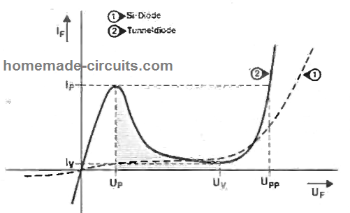
When testing the relationship between the forward voltage UF and current IF of the tunnel diode, we can find that the device has a negative resistance characteristic between the peak voltage Up and the valley voltage Uv, as shown in the figure below.

Therefore, when a diode is powered up in the shaded region of its IF-UF curve, the forward current decreases as the voltage increases. The resistance of a diode is unquestionably negative, usually denoted as -Rd.
The design presented in this article exploits the aforementioned qualities of the tunnel diode by implementing a set of tunnel diode devices connected in series to charge the battery via the sun’s heat (not a solar panel).
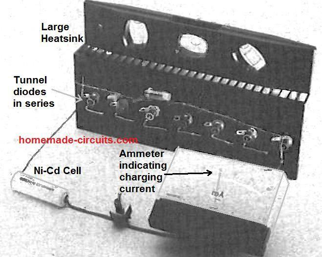
As shown in the figure below, seven or more gallium antimony (GISp) tunnel diodes are connected in series and clamped to a large heat sink, which helps prevent their power dissipation (tunnel diodes get cooler as UF rises or increases).

The heat sink is used to efficiently accumulate the heat from the sun or any other form of heat that may be applied, the energy of which needs to be converted into charging current in order to charge the proposed NiCad battery.
Converting heat into electricity using tunnel diodes (thermoelectrics)
How this particular configuration works is actually quite simple. Imagine that a normal, natural resistor R is able to discharge a battery with a current I = V/R, which means that a negative resistor will be able to initiate the charging process of the same battery, simply because the sign of I is reversed, i.e.: -I = V/-R.
Likewise, if a normal resistor allows P=PR watts of heat to be dissipated, a negative resistor will be able to deliver the same amount of watts to the load: P = -It-R.
When the load is itself a voltage source with relatively reduced internal resistance, the negative resistance must of course produce a greater voltage level in order for the charging current Ic to flow, given by the formula:
ic= δ[ σ(uf) - ubat] / σ (rd)+rbat
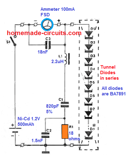
Referring to the annotation Σ(Rd), it is immediately understood that all diodes in the string sequence must operate in the -Rd region, primarily because any single diode with a +Rd characteristic could potentially terminate the target.
Testing tunnel diodes
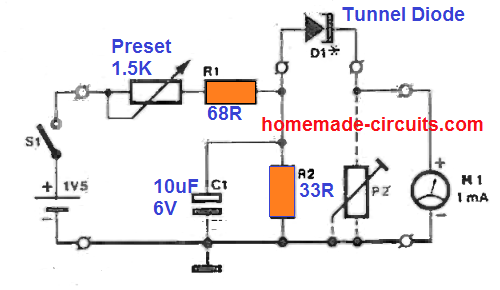
To ensure that all diodes present negative resistance, a simple test circuit can be designed as shown in the figure below.

Note that the meter should be specified to indicate the polarity of the current, as it is quite possible that the IP:IV ratio (tunneling slope) of a particular diode is very excessive, resulting in unintended charging of the battery when a small forward bias is achieved.
The analysis must be done at atmospheric temperature below 7°C (try using a cleaned out fridge) and by noting down the UF-IF curve for each diode by precisely increasing the forward bias through a potentiometer and recording the resulting IF amplitude, as shown by the meter reading.
Next, bring an FM radio close to ensure that the diode being tested does not oscillate at 94.67284 MHz (the frequency for a GISp doping level of 10-7).
If this is found to occur, the particular diode may not be suitable for the application. Determine the OF range that guarantees -Rd for nearly all diodes. Depending on the manufacturing threshold of the diodes in the available batch, this range may be as small as 180 to 230
mV。
Application Circuit
The electricity generated by the tunnel diode from the heat can be used to charge a small nickel-cadmium battery.
First determine the number of diodes required to charge the battery with the minimum current: for the above UF selection, at least seven diodes must be connected in series to provide about 45
Charging current in mA:
C [ -Σ (Rd)If][ δ (Rth-j) - RΘ]。√(Td+Ta)°C
Or when the heat sink thermal resistance does not exceed 35.3 K/W and is installed in peak sunlight (Ta 5°C), approx.
26°C. To get the most efficiency out of this NiCad charger, the heat sink must be dark to allow for the best heat exchange with the diode.
Furthermore, it must not be magnetic, considering that any type of external field, either inductive or magnetic, can lead to unstable excitation of the charge carriers within the tunnel.
This could therefore present a pipe effect to the unsuspecting; electrons could be knocked off the P-n junction at the substrate and thereby build up around the diode terminals, triggering potentially dangerous voltages depending on the metal casing.
Unfortunately, several tunnel diodes of the BA7891NG type are very sensitive to the slightest magnetic fields, and tests have proven that these diodes need to be kept horizontal with respect to the Earth's surface in order to block this.
Original prototype demonstrating solar thermal power generation using tunnel diodes

- Simple Wired Spy Bug Circuit Built Based on IC741
- Basic characteristics/working principles and application circuits of tunnel diodes
- Causes of PCB deformation How to prevent circuit board bending and warping
- How to build a drag racing timer circuit using a 7-segment display and discrete components
- Analysis of three simple electronic dice circuits
- How does RCCB work?
- Make a simple AM radio with digital circuit
- Using Monostable Trigger to Construct Pulse Delay Circuit
- AD108 frequency multiplier capable of inputting asymmetric square wave
- Digital control frequency division circuit composed of MC4018
- Can you use the new high-voltage thyristors and diodes?
- LED backlight driver module design circuit
- Bridge rectifier circuit diagram and current reversal
- Rectifier spike absorption circuit
- Microcontroller controlled flash circuit
- CdS photoresistor as electronic photometric element circuit diagram
- Proportional frequency discriminator circuit
- Lighting light and dark conversion circuit
- Internal structure of MC1411 series Darlington current drivera
- Diode, resistance and capacitance spark elimination circuit a


 京公网安备 11010802033920号