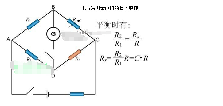
Analysis of the basic principle of measuring resistance by bridge method
Source: InternetPublisher:赔钱虎 Keywords: resistance measuring instrument wheatstone bridge Updated: 2025/01/21
The bridge method for measuring resistance is an instrument that can accurately measure resistance, a universal Wheatstone bridge.
The resistors R1, R2, R3, and R4 are called the four arms of the bridge. G is a galvanometer, which is used to check whether there is current in the branch where it is located. When no current flows through G, the bridge is said to be balanced. When balanced, the resistance values of the four arms satisfy a simple relationship, which can be used to measure resistance.

The principle of the bridge method for measuring resistance is that four resistors R0, R1, R2, and Rx are connected into a quadrilateral, which is called the four arms of the bridge. One diagonal of the quadrilateral is connected to a galvanometer, which is called the "bridge"; the other diagonal of the quadrilateral is connected to a power supply, which is called the "power diagonal" of the bridge.
E is the power supply in the circuit. The student experiment uses a dual-channel DC regulated power supply, and the voltage can be adjusted between 0-30V. R protection is a large variable resistor. When the bridge is unbalanced, the maximum resistance is used to limit the current to protect the galvanometer;
When the bridge is close to balance, the minimum value is taken to improve the sensitivity of the galvanometer. The current limiting resistor is used to limit the current. Its main purpose is to protect the galvanometer and change the sensitivity of the bridge. When the power is turned on, current flows through each branch of the bridge circuit.
When the potential between points C and D is not equal, the current 0 in the bridge circuit is ≠gI, and the pointer of the galvanometer is deflected; when the potential between points C and D is equal, the current 0 in the bridge circuit is 0=gI, and the pointer of the galvanometer points to zero. At this time, the bridge is said to be in a balanced state.
The bridge circuit is a basic way of connecting circuits in electromagnetic measurement. The advantages of the bridge circuit are sensitive testing, accurate measurement and easy use, so it has been widely used.
Bridges can be divided into DC and AC. DC bridges are mainly used to measure resistance. A DC single bridge, also known as a Wheatstone bridge, is used to measure mid-value resistances in the range of 1 to 106W; a DC double bridge, also known as a Kelvin bridge, is used to measure low-value resistances in the range of 10-3 to 1W.
In addition to measuring resistance, the AC bridge can also measure electrical quantities such as capacitance and inductance. Through sensors, some non-electrical quantities such as temperature and pressure can also be measured. It is widely used in non-electrical measurement methods.
The principle of DC single bridge resistance measurement is that the standard resistances Ra, Rb, R represented by the precision resistance box and the resistance to be measured Rx form a quadrilateral, and each side is called an arm of the bridge. The diagonal points A, C and B, D are connected to the power supply E branch and the galvanometer G branch respectively, and the diagonal BD connected to the galvanometer is called the "bridge".
When the power switch S and the galvanometer switch G are turned on, current flows through the galvanometer, but when the four bridge arms are adjusted to appropriate values, no current flows through the galvanometer. This is called "bridge balance".
Therefore, the electric potentials at points B and D are equal, that is, the currents flowing through Ra and R are the same, and the currents flowing through Rb and Rx are the same.
- Types and structures/characteristics/functions/implementations of smart sensors
- What types of power field effect tubes are there? Selection criteria for power field effect tubes
- Beautiful crown wreath made with LED
- Analysis of three simple electronic dice circuits
- Introduction of TDA4863J/4863AJ TV field scanning IC
- Experiment and production of NE555 time base integrated circuit
- Purpose and composition of amplifier circuit: low frequency voltage amplifier amplifier circuit
- Homemade air conditioner outdoor unit shutdown indicator
- Odd-frequency counter with symmetrical output waveform (SN7474, SN74163)
- Demonstration device for capacitor charging and discharging process
- 555 square wave oscillation circuit
- 555 photo exposure timer circuit diagram
- Introducing the CD4013 washing machine timer circuit diagram
- Simple level conversion circuit diagram
- 555 electronic guide speaker circuit diagram for blind people
- Circuit diagram of disconnection alarm composed of 555
- Analog circuit corrector circuit diagram
- color discrimination circuit
- Color sensor amplification circuit
- Level indication circuit


 京公网安备 11010802033920号