What types of power field effect tubes are there? Selection criteria for power field effect tubes
Source: InternetPublisher:天天都吃好吃的 Keywords: MOSFET Power MOSFET Updated: 2025/01/21
Main types of power field effect transistors
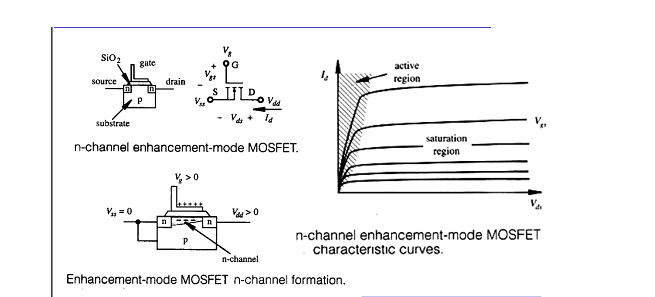
Types of power MOSFET: According to the conductive channel, it can be divided into P channel and N channel. When the gate voltage is zero, there is a conductive channel and an enhancement type. For N (P) channel devices, the gate voltage is greater than (less than) zero, and the power MOSFET is mainly N channel enhancement.
• Depletion Mode: Normally switched “ON” with no gate bias voltage, but requires a gate-to-source voltage (Vgs) to switch the device “OFF”

• Enhanced Mode: Normally off.

•N-channel MOSFET: positive voltage and current.
•P-channel MOSFET: Negative voltage and current.
• Low voltage MOSFET: BVDSS range is 0V to 200V.
• High voltage MOSFET: BVDSS greater than 200V.
Selection criteria for power FETs
How do you choose the product that meets your needs based on the manufacturer's specifications? Here are four steps you can take to select the right MOSFET.
Channel Selection
The first step in selecting the correct device is to determine whether an N-channel or P-channel MOSFET is used in a typical power supply application. When the MOSFET is connected to ground and the load is connected to the main line voltage, the MOSFET forms a low-side switch. When the low-side is open, an N-channel MOSFET should be used due to the voltage required to close or conduct the device. When the MOSFET is connected to the bus and the load is grounded, a high-side switch is used. Typically, a P-channel MOSFET is used in this topology, again due to voltage drive considerations.
Voltage and Current
The larger the rated voltage, the higher the device cost. According to practical experience, the rated voltage should be greater than the mains voltage or bus voltage. Only in this way can sufficient protection be provided to ensure that the MOSFET will not fail. For the selection of MOSFET, it is necessary to determine the maximum potential voltage that may be adopted between the drain and the source, that is, the maximum VDS, and other safety factors to be considered. Design engineers include voltage transients caused by switching electronic devices such as motors or transformers.
The rated voltage varies for different applications; typically 20V for portable devices, 20~30V for FPGA power supplies, and 450~600V for 85~220VAC applications. In continuous conduction mode, the MOSFET is in steady state and current flows continuously through the device. A pulse spike is a large surge (or spike current) flowing through the device. Once the maximum current under these conditions is determined, it is straightforward to select a device that can withstand the maximum current.
Calculation of Conduction Losses
The power loss of a MOSFET device can be calculated by Iload2*RDS(ON). Since the on-resistance changes with temperature, the power dissipation will also change proportionally. For portable designs, it is easier to use a lower voltage, but for industrial designs, a higher voltage can be used. Note that the resistance of RDS(ON) increases slightly with current. The various electrical parameters related to the RDS(ON) resistance can be found in the technical data sheet provided by the manufacturer.
Cooling requirements for computing systems
Designers must consider two different situations, the worst case and the real case. It is recommended to use the worst case calculation result because this result provides a larger safety margin to ensure that the system will not fail. There are also some measured data on the MOSFET table, such as the thermal resistance between the semiconductor junction and the environment, and the maximum junction temperature.
Switching loss is also a very important indicator. The product of voltage and current is quite large at the moment of conduction, which determines the switching performance of the device to a certain extent. However, if the system requires relatively high switching performance, a relatively small gate power QGMOSFET can be selected.
- This article will tell you the hard requirements of operational amplifiers
- Types and structures/characteristics/functions/implementations of smart sensors
- Analysis of the working principle of CMOS/CCD image sensor
- Basic characteristics/working principles and application circuits of tunnel diodes
- Make a flameless electronic candle using simple electronics and LEDs
- What is a Demultiplexer
- Touch circuit design and analysis
- Experiment and production of NE555 time base integrated circuit
- How to make a four-level water level indicator with full water alarm function
- Homemade Simple Frequency Synthesis Signal Source
- Some brief summaries on power MOSFET applications, you deserve them
- SiC MOSFET applications in automotive and power supplies
- Car window control circuit
- MOSFET gate depression test oscillator circuit diagram
- UC3625 brushless DC motor open loop speed control
- Closed loop speed control
- Power MOSFET inverter
- SI9114 uses MOSFET circuit diagram
- Charging circuit diagram using power MOSFET
- AGC loop of MOSFET


 京公网安备 11010802033920号