This article will tell you the hard requirements of operational amplifiers
Source: InternetPublisher:通通 Keywords: Operational Amplifier Updated: 2025/01/21
1. Offset zeroing
Most op amps have an offset voltage at the output even if the input voltage is the same. To make the output zero voltage, an offset nulling method is used. In most op amps, there is a small offset due to its inherent characteristics and mismatches in the input biasing arrangement.
Therefore, some op amps can provide a small output voltage at their output even when the input signal is zero. This shortcoming can be corrected by providing a small offset voltage to the input. This is called the input offset voltage. In order to eliminate or zero the offset, most op amps have two pins to enable offset zeroing. For this purpose, a Pot or Preset of a typical value of 100K should be connected between pins 1 and 5 with its wiper connected to ground. By adjusting the preset, the output can be set to zero voltage.

2. Gating or phase compensation
Op amps can sometimes become unstable, and to make them stable over the entire frequency band, a capacitor is usually connected between their strobe pin 8 and pin 1. A 47pF disc capacitor is often added for phase compensation to keep the op amp stable. This is most important if the op amp is used as a sense amplifier.
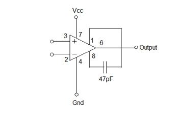
3. Feedback
As we all know, operational amplifiers have very high amplification levels, usually around 1,000,000 times. Assuming the gain of the operational amplifier is 10,000, then the operational amplifier will amplify its non-inverting input (V+) by
The voltage difference between the inverting input (V-) and the output voltage V out is
10,000 x (V+ – V-).
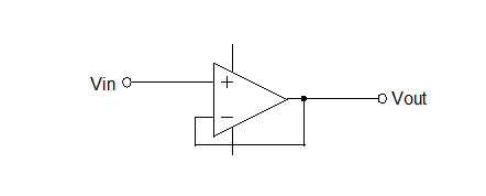
In the figure, the signal is applied to the non-inverting input and the inverting input is connected to the output. So V+ = Vin, V- = Vout. Therefore Vout = 10,000 x (Vin – Vout). So the output voltage is almost equal to the input voltage.
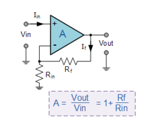
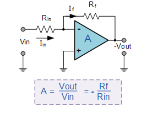
Now looking at how feedback works, simply adding a resistor between the inverting input and the output will greatly reduce the gain. Amplification can be significantly reduced by feeding a small fraction of the output voltage into the inverting input.
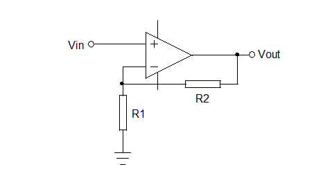
According to the previous equation, V out = 10,000 x (V+ – V-). But here a feedback resistor is added. So here V+ is Vin, and V- is R1.R1+R2 x Vout. Therefore, V out is 10,000 x (Vin – R1.R1+R2xVout). So V out = R1+R2.R1x Vin.
Negative Feedback:
The output of the op amp is connected to its inverting (–) input, so the output is fed back to the input to achieve balance. Therefore, an input signal at the non-inverting (+) input will be reflected at the output. An op amp with negative feedback will drive its output to the necessary level, so the voltage difference between its inverting and non-inverting inputs will be almost zero.
Positive feedback:
The output voltage is fed back to the non-inverting (+) input. The input signal is fed to the inverting input. In a positive feedback design, if the inverting input is grounded, the output voltage of the op amp will depend on the magnitude and polarity of the non-inverting input voltage. When the input voltage is positive, the output of the op amp will be positive, and this positive voltage will be fed to the non-inverting input, resulting in a full positive output. If the input voltage is negative, the opposite happens.
- What is a D flip-flop and how does it work?
- Diode-based clipping circuit
- How to build a drag racing timer circuit using a 7-segment display and discrete components
- Common electrical circuits: frequency-selective (bandpass) amplifier circuit
- Purpose and composition of amplifier circuit: low frequency voltage amplifier amplifier circuit
- Presettable 8-bit counter circuit
- Digital control frequency division circuit composed of MC4018
- Sine wave divider (μA747, μA795)
- Demonstration device for capacitor charging and discharging process
- Homemade Simple Frequency Synthesis Signal Source
- Quad op amp LM324
- High Q Band Pass Filter Amplifier
- Low Q Gain Band Pass Filter Amplifier
- Typical circuit of three-terminal fixed stabilizer a
- Op Amp Stabilized Power Supply Circuit Part 5
- Operational amplifier stabilized power supply circuit 4
- Alarm and protection circuit using operational amplifier
- One of the thermostatic control circuits using operational amplifiers a
- Simple sinusoidal oscillator circuit using op amp
- Speed control system block diagram circuit using operational amplifier


 京公网安备 11010802033920号