Wireless doorbell production
Source: InternetPublisher:通通 Keywords: Wireless doorbell high frequency oscillator Updated: 2024/10/28
This wireless doorbell is an electronic product analyzed by the author.
The wireless doorbell button, together with the transmitter, is embedded in the wall next to the door. The receiver can receive signals at a distance of more than 10m indoors. The transmitter uses a 9V laminated battery and the receiver uses three AA batteries. The receiver's standby current is only 0.5mA and its operating current is 140mA, as shown in Figures 1 and 2.
In the circuit of the transmitting part, A, B, resistor R2, crystal JT1 and other components of the CD4069 six-phase inverter form a high-frequency oscillator, and C, D, E, and F form the shaping and driving circuits respectively. The signal is amplified by the transistor 9018, and then transmitted into the air after resonance by L2, C2, and C3.

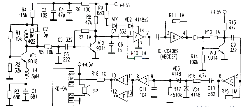
The receiving part is shown in the figure below. After the external signal is received by the loop antenna L3, it is composed of VTl and other components to form a super regenerative detector. VT2, VT3, A, B, C are used for voltage amplification, and VD3, VD4, etc. are used for large signal detection (this is designed for anti-interference). Finally, the detection signal passes through D, E, F, and outputs a square wave signal at pins (10) and (12), triggering pin (4) of the dedicated doorbell chip KD-0A. At this time, the speaker will emit a loud "ding dong" and "hello, please open the door" call sound. In the figure, L2 and L3 are made of copper foil to form an "Ω"-shaped loop antenna.

- Share the features of Wi-Fi 6 that you don’t know
- How to use FPGA and RS485 for industrial communication
- The main characteristics, advantages and disadvantages of IoT protocols
- Convenient and practical electric guitar wireless transmitter
- Homemade FM wireless microphone for teaching
- MGCT02 I/Q TDMA/AMPS l900/900 MHz Dual-Band Dual-Mode Transmitter
- RXM-921/916/903/868/433-ES Series Receiver Modules
- DKl000R OOK 315 MHz Receiver Module
- nRF401/nRF403433/315 MHz Transceiver
- rfHCS362G/362F ASK/FSK 440~310 MHz KEELOQ Code Hopping Transmitter
- USB communication circuit
- Indoor unit communication circuit
- Two-way communication circuit circuit diagram
- Long distance serial communication circuit
- CAN bus communication circuit
- Wireless transmitter circuit diagram
- Time division multiplexing stereo decoder circuit
- Design of wireless transmitting and receiving circuit based on Bluetooth
- Fiber optic transceiver circuit diagram
- Square wave generation circuit


 京公网安备 11010802033920号