Various secondary circuit diagrams and their explanations
[Copy link]
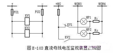
1. Figure E-103 is the circuit diagram of the DC bus voltage monitoring device. Please explain its function.
Answer: The DC bus voltage monitoring device mainly reflects the voltage of the DC power supply. KV1 is a low voltage monitoring relay. When the voltage is normal, KV1 is energized and its normally closed contact is disconnected. When the voltage drops to the set value, KV1 loses magnetism, its normally closed contact closes, the HP1 light plate lights up, and an audible signal is issued. KV2 is an overvoltage relay. When the voltage is normal, KV2 loses magnetism and its normally open contact is in the disconnected position. When the voltage is too high and exceeds the set value, KV2 is energized, its normally open contact closes, the HP2 light plate lights up, and an audible signal is issued.
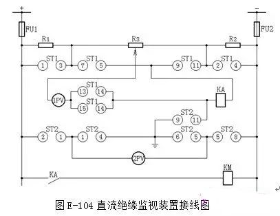
2. Explain the functions of the components in Figure E-104, the wiring diagram of the DC insulation monitoring device.
Answer: Figure E-108 is a commonly used wiring diagram of an insulation monitoring device. Under normal circumstances, the voltmeter 1PV is open-circuited, and contacts 5-7 and 9-11 of ST1 (1-3 and 2-4 of ST1 are disconnected) are connected to contact 9-11 of ST2, and the grounding relay KA is switched on. When the insulation of the positive or negative pole drops to a certain value, the bridge imbalance causes KA to operate, and a signal is sent through KM (if the insulation resistance of the positive and negative poles to the ground is equal, no matter how much the insulation drops, KA cannot operate and cannot send a signal. This is its disadvantage). At this time, 2PV can be used to check which pole has decreased insulation (when measuring "+" to ground, 2-1 and 6-5 of ST2 are connected; when measuring "-" to ground, 1-4 and 5-8 of ST2 are connected. Under normal circumstances, 2-1, 5-8, and 9-11 of the bus voltmeter conversion switch ST2 are connected, and the voltmeter 2PV can measure the voltage between the positive and negative busbars, indicating 220V.).
If the insulation of the positive pole to the ground decreases, put ST1 in gear I, its contacts 1-3 and 13-14 are connected, adjust R3 until the bridge is balanced and the voltmeter 1PV indicates zero volts; then put ST1 in gear II, at this time its contacts 2-4 and 14-15 are connected, and the total insulation resistance value of the DC system to the ground can be read from 1PV. If the insulation of the negative pole to the ground decreases, first put ST1 in gear II, adjust 3R to balance the bridge, and then put ST1 in gear I to read the total insulation resistance value of the DC system to the ground. If the positive pole is grounded, the voltage of the positive pole to the ground is zero. The negative pole indicates 220V to the ground, and vice versa when the negative pole is grounded. The voltmeter 1PV is used to measure the total insulation resistance of the DC system, and there is a resistance scale on the disk.
Since there is an artificial grounding point in this insulation monitoring device, in order to prevent other relays from malfunctioning, the current relay KA is required to have a sufficiently large resistance value, generally 30kΩ, and its starting current is 1.4mA. When the insulation resistance of any pole drops to 20kΩ, a signal can be sent. The decrease in insulation to ground and the occurrence of grounding are two situations.
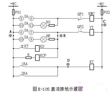
3. According to Figure E-105, explain the hazards when points A and C, points B and C, points A and B, or points A and D are grounded at the same time.
Answer: The DC system plays an important role in the substation. To ensure the long-term safe operation of a substation, there are many factors, among which the insulation problem of the DC system cannot be ignored. The DC system of the substation is relatively complex. It is connected to the terminal block, terminal box, operating mechanism box, etc. of the outdoor power distribution device through the cable trench. There is a high possibility of grounding due to cable damage, insulation aging, moisture, etc. When one pole is grounded, the fuse will not blow due to the lack of short-circuit current, and it can continue to operate, but it must be discovered and eliminated in time. Usually, the insulation resistance value of various small busbars, terminal circuits, and secondary cables of the DC system to the ground is required to be measured with a 500V megger and its value shall not be less than 0.5MΩ. The insulation of the DC circuit must be monitored regularly. Otherwise, it will bring many unsafe factors to the operation.
Now let's take Figure E-105 as an example to illustrate the hazards of DC grounding. When point A and point C in the figure are grounded at the same time, +WC and -WC form a short circuit through the earth, which may cause fuses FU1 and FU2 to melt and lose the protection power supply; when point B and point C are grounded at the same time, it is equivalent to short-circuiting the trip coil. Even if the protection operates normally, the YT trip coil will not start, and the circuit breaker will not trip. Therefore, in the case of a fault, it will trip across the level; when point A and point B or point A and point D are grounded at the same time, the protection will malfunction and cause the circuit breaker to trip. The hazards of DC grounding are not only the points mentioned above, but also many more, which will not be introduced one by one here.
Because DC grounding will cause many harms, a device is specially designed for monitoring the insulation condition of the DC system, so that it can promptly notify the on-duty personnel of DC system faults for rapid inspection and handling.
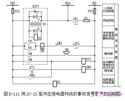
4. According to Figure E-106, the circuit breaker control circuit diagram (electromagnetic operating mechanism) with light monitoring, explain the names of each component and the operation process.
Answer: In the figure: +WC, -WC — control busbars; FU1, FU2 — fuses, R1-10/6 type, 250V; SA — control switch, LW2-1a.4.6a.40.20.20/F8 type; HG — green signal lamp, XD2 type, with 2500Ω resistor; HR — red signal lamp, XD2 type, with 2500Ω resistor;
KL — intermediate relay, DZB-115/220V type; KMC — contactor; KOM — protection output relay; QF — circuit breaker auxiliary switch; WCL — closing busbar; WSA — accident tripping busbar; WS — signal busbar; YT — circuit breaker tripping coil; YC — circuit breaker closing coil, FU1, FU2 — fuse, RM10-60/25 250V; R1 — additional resistor, ZG11-25 type, 1Ω; R2 — additional resistor, ZG11-25 type, 1000Ω; (+) WTW — flashing busbar.
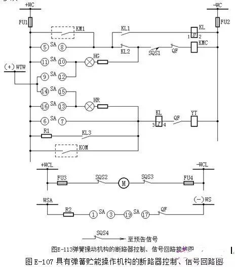
5. According to Figure E-107, the control and signal circuit diagram of the circuit breaker with a spring energy storage operating mechanism explains the names of each component and the operating process.
Answer: Figure E-113 is the circuit breaker control and signal circuit of SW4-110 circuit breaker with spring operating mechanism. In its closing coil, there is a spring with stored energy locking contact SQS1. Only after the spring is stored energy can it close. When there is an automatic reclosing switch, if it recloses on a permanent fault, the spring does not have time to store energy (9S is required), so it cannot reclose for the second time. For reliability, an "anti-jump" circuit is still added.
When KAC is started by KQT of the trip position relay, one end of the KQT coil should be connected between SQS and QF. If connected before SQS according to the previous wiring, when KAC is activated and recloses to a permanent fault, the spring energy is released, SQS is opened, KQT loses power, and the KAC start circuit is disconnected. When the capacitor in the reclosing relay is recharged enough, the spring will be recharged, SQS will be closed, the KQT coil will be energized, KAC will start, and reclosing will be performed again. This situation will be repeated many times if the control switch is not disconnected in time.
6. According to Figure E-108, the control and signal circuit diagram of the circuit breaker with hydraulic operating mechanism explains the names of each component and the operation process.
Answer: The working pressure of the hydraulic mechanism varies from manufacturer to manufacturer. Taking the CY3 model produced by Beijing Switch Factory as an example, at 20°C, the rated air storage cylinder pressure is 11.7±0.98MPa, and the rated pressure is 17.65MPa. When the temperature changes by 1°C, the pre-charge pressure changes by 0.045 MPa.
In Figure E-114, when the hydraulic pressure is lower than 14.72 MPa, the pressure contact SP4 in the closing circuit is disconnected and closing is not allowed; when the hydraulic pressure is lower than 13.73 MPa, the pressure contact SP5 in the tripping circuit is disconnected and tripping is not allowed. If the power grid operation permits, this contact can also be used to start the intermediate relay and act on the tripping.
When the pressure is lower than 15.72 MPa, the 3SP3 contact is closed, sending a signal of oil pressure reduction; when the hydraulic pressure is lower than 16.72 MPa, the contacts SP1 and SP2 are closed, and the oil pump is started to pressurize. When the oil pressure rises to 18.63 MPa, SP1 and SP2 are disconnected, and the oil pump stops pressing. When the pressure is lower than 9.8 MPa or higher than 24.5 MPa, the contacts PP1 and PP2 of the pressure gauge start KM3 to send a pressure abnormality signal. The normally closed contact of KM3 can also be used to lock the start circuit of the oil pump motor start contactor (not shown in the figure) to prevent the oil pump from starting when the oil pressure drops to zero, which may cause a slow tripping accident of the circuit breaker.
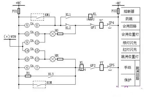

7. Based on the wiring diagram of the flashing device consisting of two intermediate relays in Figure E-109, explain the operation process.
Answer: The principle wiring of the flash device composed of two intermediate relays is shown in Figure E-109. When the position of a circuit breaker does not correspond to its control switch, the flash bus (+) WTW is connected to the negative power supply through the "non-corresponding" circuit, the signal light (HR or HG) and the operating coil (YT or YC), KM1 is started, the normally open contact of KM1 is closed, KM2 is started successively, its normally open contact short-circuits the KM1 coil, and the flash bus communicates directly with the normal power supply, and the signal light (HR or HG) is fully lit; when the KM1 contact is disconnected after a delay, KM2 loses magnetism, its normally open contact is disconnected, and the normally closed contact is closed, KM1 is started again, the flash bus (+) WTW is connected to the positive power supply through the KM1 coil, and the signal light in the "non-corresponding" circuit is half bright, repeating the above process, and a continuous flash signal is issued. KM1 and KM2 are reset with a delay to make the flash more obvious.
In the figure, the signal lamp HW of the test button SE is used for simulation test. When SE is pressed, the flash bus (+) WTW is connected to the negative power supply through the signal lamp HW, so the flash device operates according to the above sequence, causing the test lamp HW to emit a flash signal. HW is connected between the positive and negative power supplies through the normally closed contact of the button, so it also serves as a monitoring lamp for the fuse of the flash device.
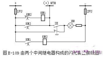
8. Explain the wiring structure and operation process of the flash device according to Figure E-110.
Answer: In Figure E-110, the flash relay is composed of KM, R, and C. When the button SE is pressed, it is equivalent to a non-corresponding circuit, the flash bus is connected to the negative power supply, the coil circuit of the flash relay KTW is connected, and the capacitor C is charged through the additional resistor R and the signal light in the "non-corresponding" circuit, so the voltage applied to both ends of KM continues to increase. When it reaches its action voltage, KM acts, its normally open contact KM.2 is closed, the flash bus (+) WTW is directly connected to the positive power supply, and the signal light is fully lit. At the same time, its normally closed contact KM.1 disconnects its coil circuit, and the capacitor C is discharged. After discharge, the terminal voltage of the capacitor C gradually decreases. When it drops to the return voltage of KM, KM resets, KM.2 is disconnected, KM.1 is closed, and the flash bus is connected to the positive power supply through KM and KM.1, and the signal light is half bright. Repeat the above process to emit continuous flashes.
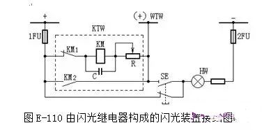
9. According to Figure E-111, explain the name and action process of each symbol component.
Answer: Central reset and repeatable accident signal devices are commonly used. The so-called central reset and repeatable accident signal means that after the circuit breaker automatically trips, in order to prevent the on-duty personnel from being disturbed by the sound signal for a long time and affecting the accident handling, the green light flashing signal can be retained and only the sound signal can be immediately removed.
In Figure E-111, KSP1 is a ZC-23 type impact relay. The diode V and capacitor C connected in parallel on the primary side of the pulse converter T play an anti-interference role; the role of the diode V connected in parallel on the secondary side is to bypass the current induced on the secondary side by the sudden reduction of the primary current of T, so that the reed relay KR does not malfunction (because the action of the reed relay has no directionality). The principle is that when the circuit breaker is tripped or the test button SE1 is pressed, there is a current increment in the primary winding of the pulse converter T, and the induced current in the secondary winding starts KR. After KR is actuated, the intermediate relay KM is started. KM has two pairs of contacts. One pair of contacts closes to start the buzzer HB and emits an audible signal; the other pair of contacts closes to start the time relay KT1. After a certain delay, KT1 starts KM1. After KM1 is actuated, KM loses its magnetism and returns, so the sound stops and the entire accident signal circuit returns to its original state.
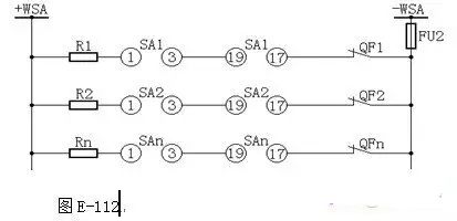
When the second circuit breaker is ready to trip, the sound is emitted, which does not correspond to the start circuit as shown in Figure E-112. The normally open contact KM2 in Figure E-111 is led by the advance signal device (see Figure E-113), so the time relay KT1 and intermediate relay KM1 used for automatic release of the sound are shared by the two sets of sound signal devices.
In order to test the integrity of the accident sound device, a test button SE1 is provided. When SE1 is pressed, KSP1 can be started, causing the device to emit a sound and return to its original state according to the above procedure.
Pressing the manual reset button will also clear the sound signal.
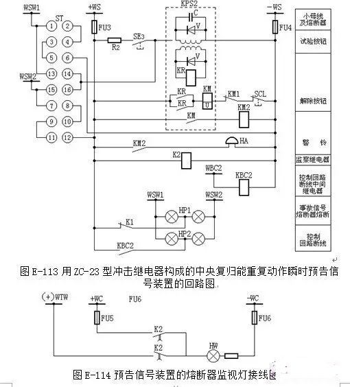
10. According to Figure E-113, explain the name and action process of each symbol component.
A: The warning signal device is a device that can automatically send out sound and light signs when the equipment fails or some abnormal operation occurs. It can help operators to find faults and hidden dangers in time so that they can take appropriate measures to deal with them and prevent the accident from expanding. Common warning signals in substations include: transformer light gas action, transformer overload, transformer oil temperature is too high, voltage transformer secondary circuit disconnection, DC circuit insulation reduction, control circuit disconnection, accident sound signal circuit fuse melting, DC voltage is too high or too low, etc.
Warning signals are generally sent from various separate relays that monitor operating parameters. For example, an overload signal is sent from an overload protection relay.
There are two types of warning signals: instantaneous warning signals and delayed signals. For some warning signals that may be issued when a short circuit occurs in the power system, such as overload, disconnection of the secondary circuit of the voltage transformer , etc., they should be issued with a delay, and the delay should be greater than the maximum removal time limit of the external short circuit. In this way, after the external short circuit is removed, the abnormalities caused by the system short circuit will automatically disappear without sending out an alarm signal, so as not to distract the attention of the operator.
At present, the widely used central reset warning signal device with repeated action has the same action principle as the accident sound signal device. The difference is that the resistor R in the corresponding starting circuit of the accident sound signal device is replaced by a light bulb, and the buzzer is replaced by an alarm. Figure E-118 shows the wiring diagram of the central reset repeatable action instantaneous warning information device composed of a ZC-23 impact relay. Its action principle is similar to that of Figure E-111. In the figure, KM1 is derived from Figure E-117 to automatically release the sound. WSW1 and WSW2 are instantaneous warning busbars.
When an abnormal situation occurs in the equipment, such as a control circuit disconnection, KBC2 will be activated, its normally open contact will close, and the normally open contacts of KBC2, HP2, WSW1 and WSW2 will be closed through the circuit +WS.
ST13-14 ST15-16 KSP2 -WS, KSP2 is activated, contact KM2 is closed, alarm bell HA sends out an audible signal, and light-emitting sign HP2 shows a "control circuit disconnection" signal. Press the release button SCL, the sound can be released (it can also be automatically released after a certain delay), and the light-emitting sign signal will not disappear until the fault is eliminated and the KBC2 contact returns. Because the ZC-23 relay is used, the signal can be repeated. In order to check the integrity of the light-emitting sign bulb frequently, a conversion switch ST is provided. When in the "closed" position, ST contacts 1-2, 3-4, 5-6, 7-8, 9-10, 11-12 are all connected, and the signal power supply +WS and -WS are connected to the small busbars WSW2 and WSW1 respectively, so that all the light-emitting sign bulbs are lit. When sending a warning signal, the two bulbs are connected in parallel, and the bulbs are bright. When one of the bulbs is damaged, the signal can still be guaranteed. When testing the light-emitting sign, the two bulbs are connected in series, so the light is dim. At this time, if one bulb is damaged, the light-emitting sign will not light up.
The warning signal device is powered by separate fuses FU3 and FU4. If FU3 or FU4 is blown, the warning signal cannot be issued, so the fuse power supply is monitored by light. Figure E-119 is the wiring diagram of the fuse monitoring light of the warning signal device. During normal operation, the fuse monitoring relay K2 is energized, its normally open contact is closed, and the white indicator light HW on the central signal screen is on; when FU3 is blown, K2 loses power, its normally closed contact is closed, and HW is connected to the flash bus (+) WTW to emit a flash.
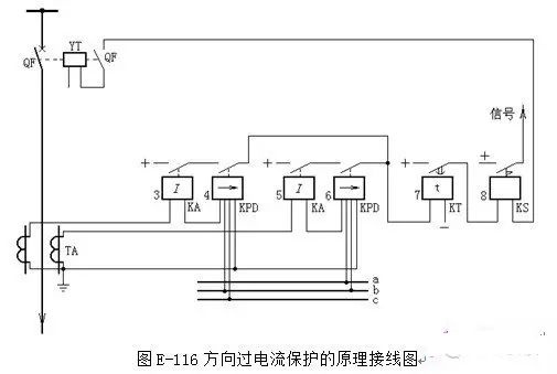
11. Based on Figure E-115, explain the structure and operation process of the line time-limited overcurrent protection.
Answer: As shown in Figure E-115, when a fault occurs in the protected line, the short-circuit current flows into KA1-KA3 through the current transformer TA. When the short-circuit current is greater than the setting value of the current relay, the current relay starts. Because the three current relay contacts are connected in parallel, as long as one current relay contact is closed, the time relay KT will be started. According to the pre-set time limit, its contacts will close and the outlet intermediate relay KOM will be started. After KOM is activated, the tripping circuit is connected, causing the QF circuit breaker to trip, and at the same time, the signal relay is activated to send an action signal. Since the action time limit of the protection is independent of the size of the short-circuit current and is fixed, it is called a time-limited overcurrent.
12. Based on Figure E-116, explain the composition and operation process of line direction overcurrent protection.
Answer: The wiring principle of directional overcurrent protection is shown in Figure E-116. Current relays 3 and 5 are starting elements, and power direction relays 4 and 6 are directional elements. 90° wiring (UbcIA and UabIc) is used. The contacts of each phase current relay and the corresponding power direction relay contacts are connected in series to achieve the effect of phase starting. Time relay 7 enables the protection device to obtain the necessary action time limit. Its contacts are closed, and a trip pulse is sent through signal relay 8 to trip circuit breaker QF.
Directional overcurrent protection, due to the installation of power directional relay, when a short circuit occurs in the line, although the current relay may be activated, the power directional relay will only be activated when the current flowing into the power directional relay is consistent with the direction specified by the power directional relay (when the specified direction is toward the line, that is, when the primary current flows from the busbar to the line), thereby tripping the circuit breaker. When the current flowing into the power directional relay is opposite to the direction specified by the power directional relay (that is, when the primary current flows from the line to the busbar), the power directional relay will not be activated, and the directional overcurrent protection will be locked, thus ensuring the selectivity of the directional overcurrent protection.
During normal operation, the direction of the load current may also be consistent with the action direction of the power direction relay, and its contacts are closed, but the current relay does not act at this time, so the entire set of directional overcurrent protection is still locked and does not act.
The action time limit of directional overcurrent protection is to adjust the protection with consistent action direction according to the reverse step principle.
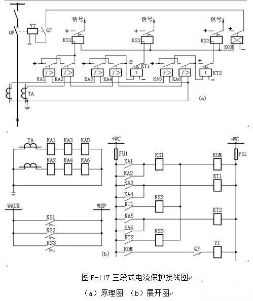
13. Based on Figure E-117, explain the composition and operation process of the three-stage current protection of the transmission line.
Answer: The principle wiring diagram and expansion diagram of the three-stage current protection of the line are shown in Figure E-117. Among them, KA1, KA2, and KS1 constitute the instantaneous current quick break of the first stage; KA3, KA4, KT1, and KS2 constitute the time-limited current quick break of the second stage; KA5, KA6, KT2, and KS3 constitute the time-limited overcurrent of the third stage. The three-stage protection acts on a common outlet intermediate relay KOM. Any protection action will start KOM, causing the circuit breaker to trip. At the same time, the signal relay of the corresponding stage will drop the card. The on-duty personnel can judge which set of protection is acting from the indication of the drop card, and then make a judgment on the approximate range of the fault.
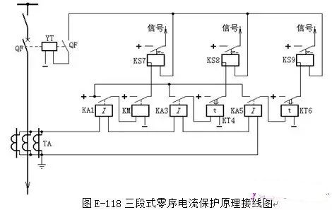
14. Based on Figure E-118, explain the composition and operation process of the three-stage zero-sequence current protection of the line.
Answer: The principle wiring of three-stage zero-sequence current protection is shown in Figure E-118. Current transformers of exactly the same model and transformation ratio are installed on the three phases of the protected line, and their secondary windings are connected in parallel and then connected to the coil of the current relay. When operating normally and when a phase-to-phase fault occurs, there is no zero-sequence current in the power grid, so IR=0, and the relay does not operate. Only when a ground fault occurs, a zero-sequence current appears. If its value exceeds the set value, the relay will operate.
In actual work, due to the inconsistent excitation characteristics of the three current transformers, when a phase-to-phase fault occurs, a large unbalanced current will be caused. In order to prevent the protection device from malfunctioning in this case, the protection action current is usually set to avoid the maximum unbalanced current.
Similar to the current protection of phase-to-phase short circuit, the zero-sequence current protection also adopts staged protection, usually three-stage. The current "four-unified" protection screen adopts four-stage. Figure E-118 is the principle wiring diagram of the three-stage zero-sequence current protection. The instantaneous zero-sequence current quick-break (zero-sequence stage I, composed of KA1, KM and KS7) is generally taken as 1.3 times of the maximum zero-sequence current 3Iom flowing through the protection device when the end of the protection line is grounded and short-circuited, and the protection range is not less than 15%~25% of the total length of the line.
The setting current of the zero-sequence II section (composed of KA3, KT4 and KS8) is generally 1.2 times the setting current of the zero-sequence I section of the next-level line, with a time limit of 0.5s, to ensure reliable operation when single-phase grounding occurs at the end of this line.
The setting current of the zero-sequence III section (composed of KA5, KT6 and KS9) can be 1.2 times the setting current of the zero-sequence II (or III) section, or greater than the maximum unbalanced current of the three-phase short circuit. Its sensitivity requires that it can operate reliably when the next-level terminal fault occurs.
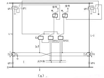
15. Based on Figure E-119, explain the structure and operation process of the double-circuit line cross-differential protection.
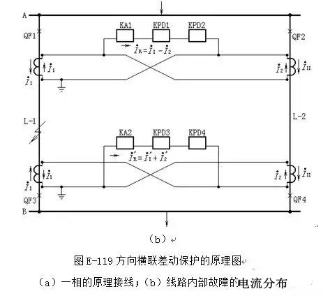
Answer: The double-circuit cross-connected differential protection device is composed of a current starting element and a power direction element. In Figure E-119 (a), the current coils of the power direction relays KPD1 and KPD2 are connected in series with the current relay KA to the current difference of the double-circuit line. The power direction relays KPD1 and KPD2 are added with the same voltage (connected to the bus voltage transformer), but with opposite polarities. When I1> I2 (i.e., a fault occurs on the same line), the torque of the left directional relay KPD1 is positive, while the torque of the right directional relay KPD2 is negative; conversely, when I2> I1 (i.e., a fault occurs on the other line), the torque of KPD2 is positive and the torque of KPD1 is negative. In this way, when a fault occurs on any of the two lines, the current relay KA starts the protection device, and the two power direction relays are used to identify the faulty line.
In normal state and external fault condition, ⅰ1=ⅰ2, ⅰR =0, and protection does not work.
When the fault occurs at point K on line L-1, ⅰ1>ⅰ2, so ⅰR =ⅰ1-ⅰ2>ⅰs, the current relay KA1 starts, the power direction relay KPD1 contacts close, and the KPD2 contacts do not close, and the protection trips the circuit breaker QF1. At the receiving end of the line, the current ⅰR flowing into the relay =ⅰ1+ⅰ2 [see Figure E-119(b)], which causes the current relay KA2 and the power direction relay KPD3 to operate, while KPD4 does not operate, thereby tripping the circuit breaker QF3. Similarly, when there is a short circuit on line L-2, KA1 and KPD2 at the sending end operate, and KA2 and KPD4 at the receiving end operate, and the circuit breakers QF2 and QF4 are tripped at the same time.
In order to prevent the cross-differential protection from malfunctioning in the event of an external fault when the single-circuit line is in operation, the protected DC power supply is locked in series through the normally open auxiliary contacts of the two switches of the double-circuit line. The protection will only work when the two switches are connected at the same time.
The operating current of the directional cross-connected differential protection should be greater than the maximum unbalanced current caused in the differential current circuit during a through fault.
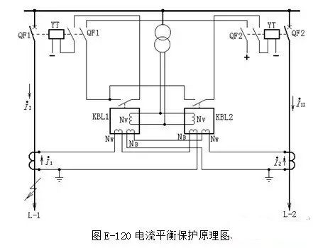
16. Based on Figure E-120, explain the composition and working conditions of the double-circuit current balance protection.
Answer: Current balance protection is another form of cross-connected differential protection. It works by comparing the absolute value of the current in the double-circuit line, as shown in Figure E-120. The current balance relays KBL1 and KBL2 each have a working coil turn Nw, a brake coil turn NB and a voltage coil turn Nv. The working coil of KBL1 is connected to the secondary side of the current transformer of line L-1, and the action torque Mw1 is generated by the current I1. Its brake coil is connected to the secondary side of the current transformer of line L-2, and the action torque MB1 is generated by the current I1. The working coil of KBL2 is connected to the secondary side of the current transformer of line L-2, and the action torque Mw2 is generated by I2. Its brake coil is connected to the secondary side of the current transformer of line L-1, and the action torque MB2 is generated by I1. The voltage coils of KBL1 and KBL2 are both connected to the secondary side of the busbar voltage transformer. The action condition of the relay is Mw>MB+Mv (Mv is the torque generated in the voltage coil).
During normal operation and external short circuit, since II=I2, KBL1 and KBL2 keep the contacts in the disconnected position due to the reaction torque Mv and the spring reaction torque Ms inside the relay, and the protection will not operate.
When a line fault occurs (such as point K of line L-1), since II>I2 and the voltage is greatly reduced, the reaction torque of the voltage coil is significantly reduced. Therefore, the action torque Mw1 generated by II in KBL1 is greater than the sum of the braking torque MB1 generated by I2 and the braking torque Mv generated by the voltage, so KBL1 operates to cut off the faulty line L-1; for KBL2, since the current II flowing through its braking coil is greater than the current I2 flowing through the working coil, that is, the braking torque is greater than the action torque, it will not operate.
It must be pointed out that on a double-circuit line of a single-ended power supply, the balancing protection can only be installed on the power transmission side, not on the power receiving side. This is because if any circuit is short-circuited, the current flowing through the working coil and the brake coil of the two balancing relays on the power receiving side will be equal, and the protection will not work.
Due to the double-circuit parallel line cross-connection differential protection and balance protection, when a short circuit occurs near the opposite side outlet, the current difference between the two lines on this side is not enough to start the protection. Only after waiting for the protection on the opposite side to act and the fault is removed, the current of the non-fault line on this side drops to zero, and then the protection on this side is activated by the fault line current to remove the fault line. This situation is called sequential action. The size of the sequential action area on the line is related to the protection setting value and the short-circuit current.
The directional relay of the cross-differential protection is connected to the bus voltage. When the three phases are short-circuited at the parallel line outlet, the voltage is zero. If the voltage circuit of the directional relay does not have a good memory effect, it will malfunction, which is called the voltage dead zone.
(I) “After tripping” position
When the handle of SA is in the "post-trip" position and the circuit breaker is in the trip position, its normally closed contact is closed, and +WC passes through FU1 SA11-10 HG and additional resistor QF (normally closed) KMC coil FU2 -WC. At this time, the green signal light circuit is connected and the green light is on, which indicates that the circuit breaker is in the post-trip position, and also indicates that the power supply, fuse, auxiliary contact and closing circuit are intact and the closing operation can be performed. However, KMC will not act because the voltage is mainly dropped on HG and additional resistor.
(ii) “Ready to close” position
When the handle of SA is rotated 90o clockwise to the "ready to close" position, SA9-10 is connected, and the green light HG circuit is (+) WTW SA9-10 HG QF (normally closed) KMC
FU2-WC is turned on, the green light flashes, and a preparatory closing signal is issued, but KMC still does not start because HG and R are connected in series in the circuit.
(III) “Closed” position
When the handle of SA is rotated 45o clockwise to the "closed" position, the SA5-8 contacts are connected, and the contactor KMC circuit is +WC SA5-8 KL2 (normally closed) QF (normally closed)
The KMC coil -WC is turned on and started, closing its contacts in the closing coil circuit to close the circuit breaker. After the circuit breaker is closed, the normally closed contact of QF opens and the normally open contact closes.
(IV) “After closing” position
After releasing the hand, the SA handle automatically rotates 45 degrees counterclockwise and returns to the vertical position (i.e. "closed"), and the SA16-13 contacts are connected. At this time, the red light HR circuit is connected by FU1
SA16-13 HR KL coil QF (normally open) YT coil FU2-WC
The red light is on, indicating that the circuit breaker is in the closed position. It also means that the tripping circuit is intact and can be tripped.
|


 Room 1530, Zhongguancun MOOC Times Building,
Block B, 18 Zhongguancun Street, Haidian District,
Beijing 100190, China
Tel:(010)82350740
Postcode:100190
 京公网安备 11010802033920号


 提升卡
提升卡 变色卡
变色卡 千斤顶
千斤顶