@[TOC]
I still remember that I started learning about microcontrollers when I was a freshman. At that time, I came into contact with infrared reception and communicated normally, using the matching remote control. Later, I discovered that there is an infrared transmitter on the development board in the laboratory. In this case, why not make an infrared remote control?
Just do it. I still remember that during the summer vacation of my sophomore year, I had nothing to do at home, so I wanted to make an infrared remote control to control the electrical appliances at home. The first thing I wanted to control was the TV at home (Skyworth).
Silly: It was a TV remote control at the time, and I used the original infrared receiving program to receive it. I found that even if I kept pressing a button, its code would always change (laughing). I was probably still in a state of ignorance at the time, and it was always there. I didn't find the reason. Later I heard that I need to use an oscilloscope (or logic analyzer) to measure it. Since I don't have these things, I put it aside.
In the second semester of my sophomore year, I spent more than 20 yuan to buy a small logic analyzer, and I fiddled with it again. I used infrared reception and the logic analyzer, plus a remote control, and messed around. , it can be regarded as being able to realize some simple control of laboratory air conditioning, which can be regarded as basically successful.
Why do you need a remote control again? There are two reasons:
One: Because my roommate was in the study room downstairs, others always turned on the air conditioner at a very low level. His body couldn't bear it, so he thought of turning it up a little. However, his phone didn't have infrared, and his air conditioner didn't have a remote control. Then you can only do one.
Second: Because Lichuang EDA recently held an event, since there is an event, there must be rewards. To implement the spirit of free prostitution, you must participate, but free prostitution also has principles, (you must make something), So let’s make an infrared remote control.
Infrared remote control consists of two parts: sending and receiving. The transmitting end uses a microcontroller to encode and modulate the binary signal to be sent into a series of pulse train signals, and transmits the infrared signal through the infrared transmitting tube. Infrared reception completes the reception, amplification, detection, shaping, and demodulation of remote control coded pulses of infrared signals.
The main component of the infrared remote control transmitting device is an infrared light-emitting diode, and the transmission power of a single infrared light-emitting diode is about 100mw.
The control distance of infrared remote control is about 10 meters.
The most common data protocol is : ==NEC encoding. == There are other agreements: ITT, a Nokia, NRC, Sharp, Sony
The composition of the infrared remote control protocol: generally consists of a boot code, a user code, a key code, a repeat code, a reverse key code, an end code, etc.
Infrared remote control carrier frequency : 33K, 36K, 36.6K, 38K, 40K, 56K. 38K is commonly used, and 37.916K is the most accurate. Infrared carrier duty cycle: 1/3, 1/2, 1/4 is less commonly used.
Infrared remote control transmission adopts PPM encoding method. When transmitting, a set of 108ms encoding pulses will be emitted. The remote control encoding pulse consists of a preamble code, a 16-bit address code (an 8-bit address code, the inverse code of the 8-bit address code), and a 16-bit operation code (an 8-bit operation code, the inverse code of the 8-bit operation code).
By checking the user code, each remote control intelligently controls the action of a device, which can effectively prevent interference between multiple devices.
The code must be followed by the inverse code to detect the correctness of code reception, prevent misoperation, and enhance the reliability of the system.
The preamble code is the starting part of a remote control, consisting of a 9ms high level (start code) and a 4.5ms low level (result code), which serves as a preparation pulse for receiving data.
The combination of a pulse width of 0.56ms and a period of 1.12ms represents a binary "0", and a combination of a pulse width of 1.68ms and a period of 2.24ms represents a binary "1".
1. Microcontroller configuration register, enable P32 pin falling edge interrupt and timer interrupt. It is recommended to use 8-bit automatic reloading for the timer, with a maximum timing of 96us.
2. When the boot code 38KHz infrared irradiates the receiver, the receiver outputs a low level to the P3.2 pin of the microcontroller, triggering a falling edge interrupt.
3. First save the time value of the timer, and then clear the timer’s custom variable (not the register)).
4. The next time 38KHz comes, continue to trigger the falling edge interrupt. Same as before. The time value is saved first and then the custom variable is cleared.
5. The time difference between the two falling edges mentioned above is the most basic time difference of the infrared remote control.
6. According to the length of time, after judging that the correct boot code appears, save the subsequent 32 lengths of time (i.e., continuous falling edges, time difference)).
7. Divide into 4 times and judge the time length of 8-bit data respectively. 1's and 0's are identified according to the protocol. 8 bits are low bit in front and high bit in back.
8. The sequence of the entire NRC protocol is: 9ms+4.5ms boot code, 8-bit user machine code, 8-bit machine inverse code, 8-bit key code, and 8-bit key inverse code.
==Supporting infrared remote control code==
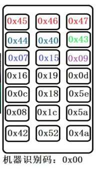
First of all, there is an air conditioner remote control and an infrared receiver. You also need a logic analyzer and the accompanying host computer software.
First we need to know the encoding format of the air conditioner remote control
We connect one channel of the logic analyzer to the data pin of the infrared receiver, and then turn on the host computer logic analyzer.
Click start to start the collection. During the collection process, we press a button on the remote control to be decoded.
After that, a waveform will appear on the logic analyzer, as follows:
 Here I have written out whether the waveform represents 0 or 1. Remember that the encoding format is:
==Each 8 binary data is one byte, and then these 8 binary data are sent from low to high. For example: 1011 0010 means the first byte, then we know that the first one is the low bit, and the next one is the high bit. So from high to low it should be 0100 1101. The correct encoding is 4D, and the same is true for the following. ==
What I am testing here is the command to turn off the air conditioner, so I conclude that the command to turn off the air conditioner is
uchar code ir_close[6]= {0x4D,0xB2,0xDE,0x21,0x07,0xF8};//关空调指令The subsequent tests are similar, so I won’t write them out.
Below are some codes for Midea air conditioner (model: RN02U/BG).
== Fixed encoding == The following encodings are fixed and do not change.
unsigned char shangxiafeng[6] = {0x9D,0x62,0xAF,0x50,0x20,0xDF}; //上下风
unsigned char zuoyoufeng[6] = {0x9D,0x62,0xAF,0x50,0xE0,0x1F};  //左右风
== Unfixed encoding == The following encodings are not fixed, but are == combined encodings ==. Regarding the format of combined encoding:
4D B2: These two codes are fixed. The third byte: indicates the wind speed. The fourth byte: indicates the inverse code of the wind speed. The fifth byte: the high 4 bits indicate the mode, and the low four bits indicate the sixth word of the temperature. Section: The high 4 bits represent the inverse code of the mode, the low 4 bits represent the inverse code of the temperature 4D B2 FD 02 3A C5 FD 02 represents the wind speed 3 C represents mode A 5 represents the temperature
Mode:
1. Auto 1110 E 2. Cooling 1111 F 3. Dehumidification 1101 D 4. Heating 1100 C
Wind speed
AU: FD 02 20%: FF 00 40%: F9 06 60%: FA 05 80%: FC 03 F% (test unsuccessful): FC 03
Temperature: 17: 0000 0 18:1000 8 19:1100 C 20:0100 4 21:0110 6 22:1110 E 23:0101 A 24:0100 2 25:1100 3 26:1011 B 27:1001 9 28:0001 1 29:1010 5 30:1101 D
 For more details, please find the complete code.
Burn the program to the development board and verify it.
I use the STC8A8K-44-pin microcontroller as the main control chip, mainly because I still have two on hand. This function is also very powerful, but I haven't used it, so it's a bit of a waste.

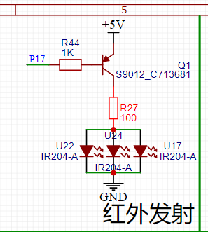
The infrared circuit didn't work properly before. After tinkering with it for a long time, it just didn't work. There was an infrared transmitter on the development board before. I replaced it with that circuit and it worked.
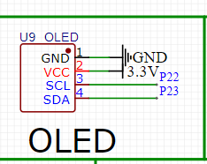
Why do I need to add a display screen? This is because I need to display some status information of the current air conditioner, so that I can clearly and intuitively see the current status of the air conditioner, which facilitates my next operation.
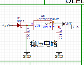
There is nothing to say, just convert 5V into 3.3V for use.
Because it is a remote control, it must be portable, and a battery must be added. The battery is about 3.7V. My microcontroller works at 5V, so it must be converted to 5V.

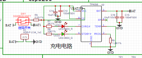
Since we all use batteries, we must have a charging circuit. When the battery is out of power, you can't just take it off, charge it and then put it back on. It's too troublesome. Just plug it in and charge it.
Because there are many control buttons for the air conditioner, I used a 4x4 matrix button here, so that fewer IO ports can be used to control more buttons and save microcontroller resources.

This is an extended function, and the current time will be displayed on the screen later, so that the resources of the microcontroller can be better utilized.

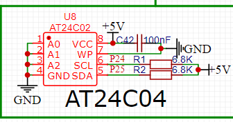
This is also an expansion module. If you want to make it a learning infrared remote control later, then saving data will definitely be indispensable. This module can store data, and the speed is not slow.
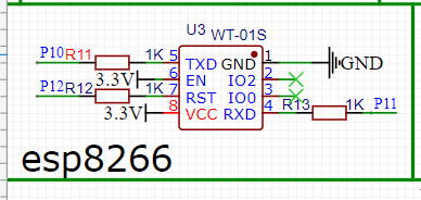
This is also an extension module. If you want to make it network-connected in the future, you only need to put the remote control next to the air conditioner, and you can control the opening and closing of the air conditioner through your mobile phone to achieve remote control. This application is also very convenient.
First of all, we need to make sure there is no problem with the power supply. Because this is an internal crystal oscillator, we don’t need to worry about the crystal oscillator. After welding this part, we can see if we can burn the program to the microcontroller.
 If there are no problems in this part, it will basically be successful, and the follow-up will be auxiliary.
The boost circuit boosts the battery's 3.7V to 5V.

This part is the expansion circuit, we need to solder it, there will be no impact if we don’t solder it.

On the back are some resistors for the buttons, a triode for the buzzer, and an infrared triode.

After welding this part, we are basically done.

Finally, when we download the program, this interface will appear, and press each button (see the silk screen) to perform the corresponding function.


All reference designs on this site are sourced from major semiconductor manufacturers or collected online for learning and research. The copyright belongs to the semiconductor manufacturer or the original author. If you believe that the reference design of this site infringes upon your relevant rights and interests, please send us a rights notice. As a neutral platform service provider, we will take measures to delete the relevant content in accordance with relevant laws after receiving the relevant notice from the rights holder. Please send relevant notifications to email: bbs_service@eeworld.com.cn.
It is your responsibility to test the circuit yourself and determine its suitability for you. EEWorld will not be liable for direct, indirect, special, incidental, consequential or punitive damages arising from any cause or anything connected to any reference design used.
Supported by EEWorld Datasheet