|
3257 views|0 replies
pengshulin
Currently offline
|
The OP
Published on 2019-12-6 12:02
Only look at the author
This post is from Integrated technical exchanges
| |
|
|
||
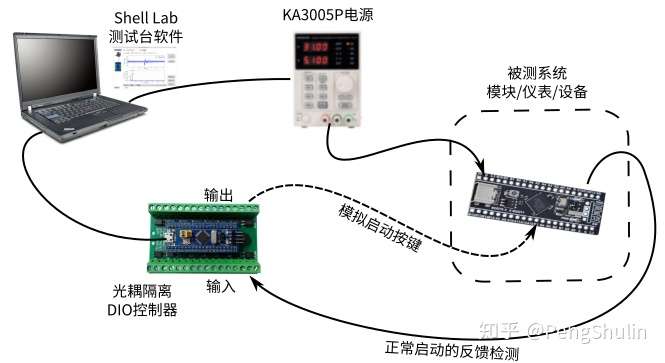
- 【Posts】Controlling Hardware with Python - Low Voltage Startup and Reliability Testing
- 【Posts】Controlling Hardware with Python - Automating Frequency Response Testing of Conditioning Circuits
- 【Posts】Controlling Hardware with Python - Measuring the Resonant Frequency of an Object Using the ADXL335 Accelerometer
- 【Posts】Smart Hardware and Machine Vision: Based on Raspberry Pi, Python and OpenCV
- 【Posts】Some questions about starting xenon lamps
- 【Posts】Has anyone encountered the situation where the capacitor pulls down the voltage?
- 【Posts】Please tell me why this machine often burns the starting resistor at the customer's place
- 【Posts】Python is now officially the second most popular programming language
- 【Download】Mobile phone hardware and reliability test items and standards
- 【Download】LED lamp reliability test method and cost control
- 【Download】Hardware implementation of low voltage, low pass filter for MC68HC05F2 DTMF output
- 【Download】Python Hardware Programming Practice
- 【Download】STM32? microcontroller system memory boot mode
- 【Download】Delta PLC routine_Use Delta PLC485 communication to control 11 INVT inverters to start and stop speed settings
- 【Download】Soft starter based on single chip microcomputer control
- 【Download】Teaching plan for \"Star-Delta Step-Down Starting Control Circuit\"
- 【Design】PhyWhisperer-USB: Hardware-based USB 2.0 monitor and trigger platform controlled by Python
- 【Design】Doubly-fed wind power generation system based on direct power control and its low voltage ride-through source code
- 【Design】TWR-MC-LV3PH: Low voltage, 3-phase motor control towersystem module
- 【Design】STC Cold Start Free Downloader [Hardware Version]
- 【Design】NCP1365XS1GEVB: Low Power Offline Constant Current & Constant Voltage Primary Side PWM Current Mode Controller with High Voltage Startup Current Source Evaluation Board
- 【Design】Design a car cold start boost circuit using the MAX15005 current mode controller
- 【Circuits】AC contactor low voltage starting circuit 2
- 【Circuits】One of the AC contactor low voltage starting circuits
- 【Circuits】Overcurrent protection circuit for generator low voltage starting a
- 【Circuits】Overcurrent protection circuit for generator low voltage start b
- 【Circuits】Production of 12V battery controller (low voltage protection circuit)
- 【Circuits】Start control circuit with phase sequence and phase loss protection
- 【Articles】Analyzing Hardware Reliability Test Design Using Examples
- 【Articles】Detailed explanation of hardware reliability testing methods
- 【Articles】Brief analysis of LED lamp reliability test methods and cost control issues
- 【Articles】Diodes Incorporated's low-voltage Hall-effect latches enable high-sensitivity sensing in industrial and automotive motor control product applications
- 【Articles】Part4_lesson2---Analysis of the hardware startup process of ARM processor
- 【Articles】STM32 cannot start after hardware reset
-
Controlling Hardware with Python - Automating Frequency Response Testing of Conditioning Circuits
Reprintedfrom:"UsingPythontocontrolhardware43-Automationoffrequencyresponsetestofconditioningcircuit"Thistime,weusetheF5520AandF8808AintroducedearliertomeasurethefrequencyresponseofananalogconditioningcircuitThepurposeofthisexperimentistoau ...
-
Controlling Hardware with Python - Measuring the Resonant Frequency of an Object Using the ADXL335 Accelerometer
Reprintedfrom:"UsingPythontocontrolhardware38-MeasuringtheresonantfrequencyofanobjectusingtheaccelerometerADXL335"Physicstellsusthatanyobjectwillhaveresonance(suchasthetuningforkusedinhighschoolphysicsexperiments)Someobjectsmayhavemorethano ...
-
OPEN SCOFIELD WINTER WARDROBE
[img]https://wwwnet/images/2024/11/14/1f9dff95d3bc981f8img][img]https://wwwnet/images/2024/11/14/2a81ca07f0c52991bimg]
- Newbie Report Newbie Report
- How to use CAN communication to control the inverter?
- The Structure and Interpretation of Computer Programs (2nd Edition)
- Teacher maychang's new work - interesting video about the history of electronic technology: the debate between AC and DC
- Detailed description of the debugging document of the NUCLEO-G431RB+IHM08-V4 three-resistor FOC (5.4.1 library) motor control board
- Pybricks: MicroPython for LEGO
- STM32 environment construction under MDK compiler
EEWorld Datasheet Technical Support
-
Qualcomm launches its first RISC-V architecture programmable connectivity module QCC74xM, supporting Wi-Fi 6 and other protocols
On November 14, Qualcomm announced the launch of two connectivity modules, QCC74xM and QCC730M, f
-
It is reported that memory manufacturers are considering using flux-free bonding for HBM4 to further reduce the gap between layers
On November 14, according to Korean media ETNews, Samsung Electronics, SK Hynix, and Micron are a
-
ON Semiconductor CEO Appears at Munich Electronica Show and Launches Treo Platform
During Electronica, ON Semiconductor CEO Hassane El-Khoury was interviewed by Power Electronics N
- AMD launches second-generation Versal Premium series: FPGA industry's first to support CXL 3.1 and PCIe Gen 6
- SEMI: Global silicon wafer shipment area increased by 6.8% year-on-year and 5.9% month-on-month in 2024Q3
- TSMC's 5nm and 3nm supply reaches "100% utilization" showing its dominance in the market
- LG Display successfully develops world's first stretchable display that can be expanded by 50%
- Seizing the Opportunities in the Chinese Application Market: NI's Challenges and Answers
- New diaphragm-free solid-state lithium battery technology is launched: the distance between the positive and negative electrodes is less than 0.000001 meters
- Photoresist giant JSR Korea EUV MOR photoresist production base started construction, expected to be put into production in 2026
- Problems with STM32 and passive buzzer playing sound
- Embedded Tutorial_DSP Technology_DSP Experiment Box Operation Tutorial: 2-28 Building a Lightweight WEB Server Experiment
- OPA847IDBVR op amp domestic replacement
- AG32VF407 Test UART
- [Digi-Key Follow Me Issue 2] Chapter 1: Sharing on receiving the goods
- What model is this infrared receiver? Which model can be used instead? Thank you
- Selling brand new unopened ZYNQ 7Z020 FPGA core board
- The LORA module used in the lithium battery-powered water meter setting can save energy when 100 water meters are installed in one corridor.
- I would like to ask, when a port is set to RX0, is it necessary to set the input and output direction of this port?
- Why is this year so difficult? It’s even more difficult than during the pandemic. I’m 30 and facing unemployment. I’m so confused.
- Ask about the voltage regulator test question
- [Xiaohua HC32F448 Review] About Xiaohua Semiconductor's UART interrupt sending and PRINTF construction and redirection
- 【BIGTREETECH PI development board】 HDMI output test
- 【BIGTREETECH PI development board】+08. Audio test (zmj)
- [Xiaohua HC32F448 Review] +RTC electronic clock
- # STM32H7S78-DK Development Kit Three-week Review: Implementation and Analysis of Simple Sound Collection and Storage Using SD Card Reading and Writing
- [STM32H7R/S] Review⑧ nano edge ai studio training a model--Part 1
- [2024 DigiKey Creative Competition] A "fortune-telling" artifact based on Raspberry Pi
- New energy vehicle on-board AC slow charging and maintenance
- Embedded Engineer AI Challenge Camp (Advanced): Deploy InsightFace algorithm on RV1106 for real-time face recognition of multiple people
- I want to make a self-driving car. I saw one on Bilibili that costs 300 yuan. I am hesitant.
- [K230 Embedded AI Development Board Review] + License Plate Recognition and Billing Management
- How to deploy LVGL free graphics library on low-cost ARM platform, based on Allwinner T113-i
- Please help me analyze the reasons why EMI fails.
- ChatTTS is really awesome!
- 参会有好礼 | 2024 瑞萨电子MCU/MPU工业技术研讨会
- 深圳站:11月30日(周六)深圳湾万怡酒店
上海站:12月06日(周五)上海喜玛拉雅酒店
奖励设置:现金红包、螺丝刀套装或30元京东卡
- Littelfuse 新品赋能电子产品安全可靠并高效, 10+挑战等你探索!
- Littelfuse 应用赋能星球,覆盖了诸多应用痛点及解决办法,邀请工程师一起探索,解锁更多设计力!
- 了解英飞凌新品AIROC™ CYW5591x 无线MCU,答题赢好礼!
- 无线键盘鼠标套装、智能音箱、登山包、收纳包
- 下载资料赢好礼!看Vicor模块化电源解决方案如何推动创新
- 活动时间:即日起-2024年12月31日
如何参与:点击活动页内您想了解的模块,找到资料下载即可参与抽奖,活动结束后统一发奖!
- 有奖活动|英飞凌高密度双相电源模块为高性能运算平台而生
- 活动时间:即日起-12月15日
活动奖励:蓝牙音箱、氮化镓充电器套装、黑色小背包
- 免费申请 | MPS MIE 系列隔离式稳压 DCDC 模块!
- 诚邀您按实际情况填写申请!MPS 对申请信息进行审核,为通过申请的网友发送样品。(每人最多5片)
拿到样片的网友可参加第三期评测活动哦!奖品多多~快来申请免费模块吧!
- 本周精选下载推荐:电源管理基础Dummies
- 本周小编给大家带来一本超简单、超干货的电子书——《电源管理基础Dummies》!内容深入浅出,排版舒服简洁,分分钟能get到电源管理最核心的知识内容。
EEWorld
subscription
account

EEWorld
service
account

Automotive
development
circle

About Us Customer Service Contact Information Datasheet Sitemap LatestNews
- I want to get started with 51PCB, what should I do?
- I want to get started with microcontroller UI, what should I do?
- I want to get started with machine learning competitions, what should I do?
- For the introduction to PCB and hardware, please give a learning outline
- For an introduction to neural network model algorithms, please give a learning outline
- Please give a study outline for the introduction to neural networks for data analysis
- How long does it take to get started with fpga
- How to get started with smt
- How to learn MCU
- How to use gemini in China


 Room 1530, Zhongguancun MOOC Times Building,
Block B, 18 Zhongguancun Street, Haidian District,
Beijing 100190, China
Tel:(010)82350740
Postcode:100190
 京公网安备 11010802033920号


 提升卡
提升卡 变色卡
变色卡 千斤顶
千斤顶