introduction
Frequency divider is a basic circuit in digital system design. According to the needs of different designs, we will encounter even frequency division, odd frequency division, half-integer frequency division, etc. Sometimes it requires equal duty cycle, sometimes it requires non-equal duty cycle. . Multiple forms of frequency division are sometimes required in the same design. Counters or cascades of counters are usually used to form various forms of even frequency division and odd frequency division with non-equal duty cycles, which are relatively simple to implement. However, it is more difficult to realize half-integer frequency division and odd-number frequency division with equal duty cycle. This article uses VHDL hardware description language, through the QuartusⅡ3.0 development platform, and uses Altera's FPGA to design a more general frequency divider that can meet the above various requirements.
1. Circuit design
Using FPGA to implement a half-integer frequency divider, you can use the following method: design a modulo N counter, and then design a pulse deduction circuit, and deduct one pulse for every two pulses to achieve a frequency division with a frequency division coefficient of N-0.5 device. The pulse subtraction circuit consists of an XOR gate and a 2-frequency divider. This design is based on the principle of half-integer frequency divider, adding an enable control signal to the XOR gate, and controlling the counting status value of the XOR gate and counter to realize multiple forms of frequency division with the same circuit, as shown in the figure 1 shown.

2. Implementation of VHDL language
Now by designing a frequency divider that can achieve 8.5 frequency division, 17 frequency division with equal duty cycle, 2, 4, 8, 16, 32 frequency division, and 9 frequency division with duty ratios of 1:8 and 4:5, etc. A form of frequency divider, introducing the FPGA implementation of this universal frequency divider.
As can be seen from the circuit schematic diagram shown in Figure 1, the frequency divider consists of an XOR gate with an enable end, a modulo N counter and a 2-frequency divider. This design uses a D flip-flop to complete the 2-frequency divider function. Implementation method Yes: Feed back the Q inverse output terminal of the flip-flop to the input terminal D, and use a counting output terminal of the counter as the clock input terminal of the D flip-flop. The VHDL language implementation of each functional module is as follows.
1. Implementation of Modulo N Counter
When a counter is used in general design, we can call the counter module in the lpm library, or we can use VHDL language to design a modulo N counter ourselves. This design uses VHDL language to design a counter with a maximum modulus value of 16. The input ports are: enable signal en, reset signal clr and clock signal clk; the output ports are: qa, qb, qc, qd. Its VHDL language is briefly described.
2. Implementation of XOR gate with enable control
The input terminal is: xor_en: XOR enable, a and b: XOR input; the output terminal is: c: XOR output. When xor_en is high level, c outputs the XOR value of a and b. When xor_en is low level, c outputs signal b. Its VHDL language is abbreviated.
3.2 Implementation of frequency division (flip-flop) The input
terminal is: clock signal clk, input signal d; the output terminal is: q: output signal a, q1: the inverse of output signal a. Its VHDL language is abbreviated.
4. Implementation of frequency divider
This design adopts a hierarchical design method. First, design and implement each component circuit element in the frequency divider circuit, and then use the component instantiation method to call each component to realize the entire frequency divider. Its VHDL language is abbreviated.
3. Simulation results and hardware circuit testing
The purpose of this design is versatility and simplicity. As long as the above program is slightly modified, various forms of frequency division can be achieved.
1. Achieve frequency division by 8.5 and frequency division by 17 with equal duty cycle
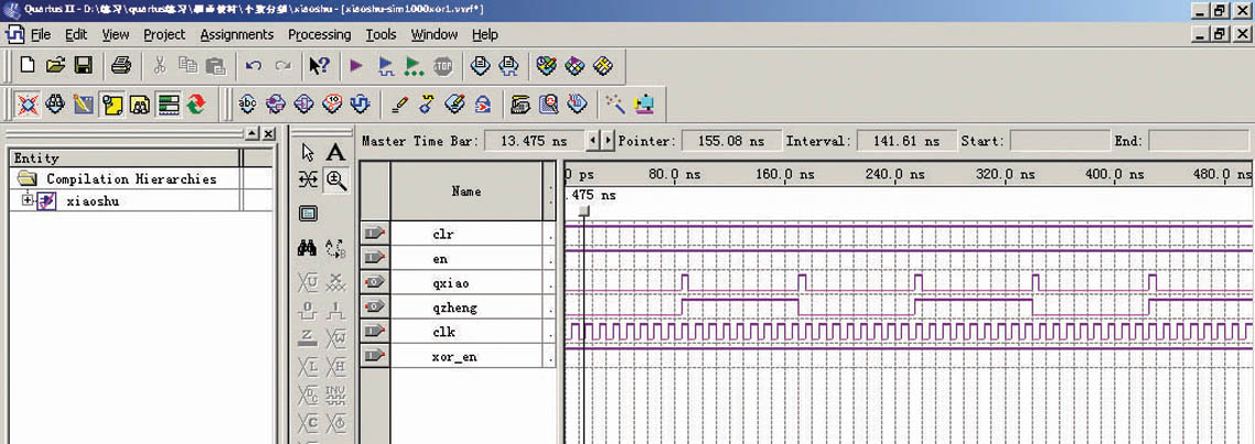
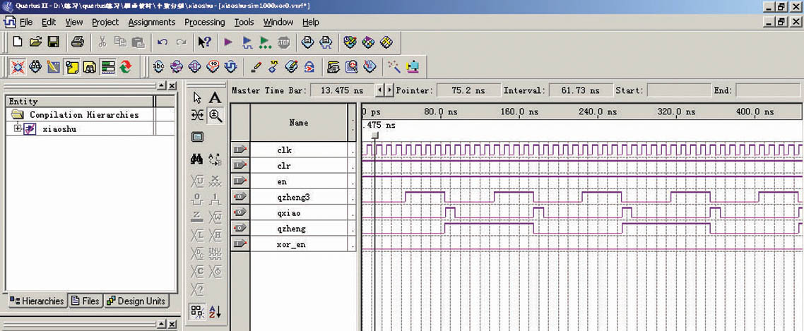
In the above program, when calling the counter module, the ports qa, qb, and qc are matched to the open state, and xor_en is set to high level at the same time. It can be seen from the compilation report that a total of 8 logic elements are occupied, and the simulation waveforms are shown in Figures 2 to 4.
Figure II

Figure 3

Figure 4 can be seen from the waveforms of qxiao and clk in the figure. Every 8.5 clock cycles, the qxiao signal generates a rising edge, thereby achieving a frequency division coefficient of 8.5. At the same time, an equal duty cycle of 17 is obtained at the qzheng end. Frequency division. Assume clk is 170MHz, then qxiao output is 20MHz and qzheng output is 10MHz.
2. Achieve divide-by-9 with duty ratios of 1:8 and 4:5
As long as xor_en of the above program is set to low level, a frequency-divided-9 signal with a duty cycle of 1:8 can be output at qxiao; a frequency-divided-9 signal with a duty cycle of 4:5 can be output at qzheng2. It also only occupies 8 logic elements. The simulation waveform is as follows.
3.To achieve frequency division of 2, 4, 8, 16 and 32 with equal duty cycle,
just set xor_en in the above program to low level and set the maximum counting value of the counter module to 16. The simulation waveform is as follows.
It can be seen that as long as the counting status value of the counter is slightly changed and the XOR gate is gated, the above-mentioned various forms of frequency division can be realized. This design has been tested on the test platform composed of Altera's EP1K50QC208-3, and the performance is good.
Conclusion
We have used the above-mentioned various forms of frequency dividing when designing simulated radar pulse signals and developing spread spectrum chips with FPGA. This article aims to introduce a method to implement multiple frequency divisions required when developing FPGA. If there are many frequency division forms required in the design, you can directly use this design and make slight changes to the program to meet your own design requirements. . If the design requires fewer frequency division forms, you can use part of this design program to save resources.
references
1 Xu Zhijun, Xu Guanghui eds. Development and Application of CPLD/FPGA, Electronic Industry Press
2 Hou Boheng, Gu Xin eds. VHDL Hardware Description Language and Digital Logic Circuit Design, Xi'an University of Electronic Science and Technology Press
3 ALTERA Company, Introduction to QuartusⅡ
Previous article:Implementation of TMS320VC5402 HPI bootstrapping based on USB2.0 bus
Next article:Application of ADSP2189M in the development of automatic ship identification system
- Huawei's Strategic Department Director Gai Gang: The cumulative installed base of open source Euler operating system exceeds 10 million sets
- Analysis of the application of several common contact parts in high-voltage connectors of new energy vehicles
- Wiring harness durability test and contact voltage drop test method
- Sn-doped CuO nanostructure-based ethanol gas sensor for real-time drunk driving detection in vehicles
- Design considerations for automotive battery wiring harness
- Do you know all the various motors commonly used in automotive electronics?
- What are the functions of the Internet of Vehicles? What are the uses and benefits of the Internet of Vehicles?
- Power Inverter - A critical safety system for electric vehicles
- Analysis of the information security mechanism of AUTOSAR, the automotive embedded software framework
 Professor at Beihang University, dedicated to promoting microcontrollers and embedded systems for over 20 years.
- Innolux's intelligent steer-by-wire solution makes cars smarter and safer
- 8051 MCU - Parity Check
- How to efficiently balance the sensitivity of tactile sensing interfaces
- What should I do if the servo motor shakes? What causes the servo motor to shake quickly?
- 【Brushless Motor】Analysis of three-phase BLDC motor and sharing of two popular development boards
- Midea Industrial Technology's subsidiaries Clou Electronics and Hekang New Energy jointly appeared at the Munich Battery Energy Storage Exhibition and Solar Energy Exhibition
- Guoxin Sichen | Application of ferroelectric memory PB85RS2MC in power battery management, with a capacity of 2M
- Analysis of common faults of frequency converter
- In a head-on competition with Qualcomm, what kind of cockpit products has Intel come up with?
- Dalian Rongke's all-vanadium liquid flow battery energy storage equipment industrialization project has entered the sprint stage before production
- Allegro MicroSystems Introduces Advanced Magnetic and Inductive Position Sensing Solutions at Electronica 2024
- Car key in the left hand, liveness detection radar in the right hand, UWB is imperative for cars!
- After a decade of rapid development, domestic CIS has entered the market
- Aegis Dagger Battery + Thor EM-i Super Hybrid, Geely New Energy has thrown out two "king bombs"
- A brief discussion on functional safety - fault, error, and failure
- In the smart car 2.0 cycle, these core industry chains are facing major opportunities!
- The United States and Japan are developing new batteries. CATL faces challenges? How should China's new energy battery industry respond?
- Murata launches high-precision 6-axis inertial sensor for automobiles
- Ford patents pre-charge alarm to help save costs and respond to emergencies
- New real-time microcontroller system from Texas Instruments enables smarter processing in automotive and industrial applications
- LOTO Practice [Dry Goods] 2- Quick Application of Voltage Comparator
- GD32E230C Test 2: I2C and EEPROM
- 【XMC4800 Relax EtherCAT Kit Review】+DAVE integrated development environment construction and demo operation
- Design of data acquisition card based on FPGA.pdf
- Xunwei 4412 development board cross-compiles Qt application code
- Actual development and experience of the first phase
- 【National Technology N32G430】02 Small expansion, communication from top to bottom
- PCB and PCB LAYOUT (dry goods sharing)
- BlueNRG beacon+serial port transparent transmission
- KiCad Diff Tool

 【Follow me Season 2 Episode 1】-Mission Code (Adafruit Circuit Playground Express Development Board)
 【Follow me Season 2 Episode 1】Source code
 5962-9065901HXA


 京公网安备 11010802033920号