OBC is a power electronic device for charging automobile power batteries, that is, an on-board charger, or OBC for short.

I. Definition
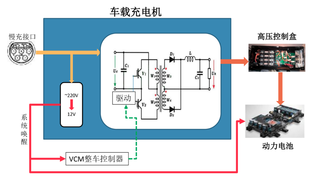
The on-board charger of electric vehicles adopts high-frequency switching power supply technology. Its main function is to convert AC 220V into high-voltage DC to charge the power battery to ensure the normal driving of the vehicle. At the same time, the on-board charger provides corresponding protection functions, including overvoltage, undervoltage, overcurrent, undercurrent and other protection measures. When the charging system is abnormal, the power supply will be cut off in time.
2. Internal Structure


The interior of the on-board charger can be divided into three parts: main circuit, control circuit, wiring harness and standard parts

Conversion principle:
220Vac is filtered by the EMI filter circuit, rectified by an AC-DC converter, rectified into DC, and then boosted by the PFC power factor calibration circuit. It is then sent to the switch and transformer for variable frequency boosting. After the LLC is rectified and filtered for the second time, high-voltage DC is output to charge the power battery (the first 220Vac is rectified to 310Vdc, the voltage is not enough, and it needs to be boosted and converted twice)
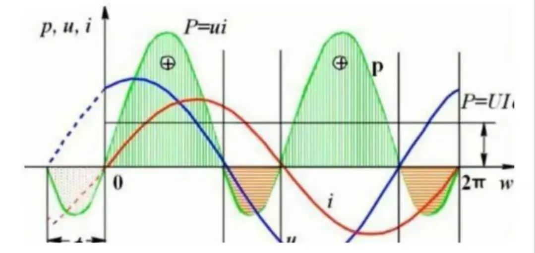
1. Main circuit: The main circuit can usually be divided into two stages. The front stage is the power factor correction PFC module, which improves the input power factor and suppresses high-order harmonics; the back stage is the DCDC converter, that is, the LLC module, which meets the current and voltage requirements of battery charging and realizes electrical isolation (PFC: power factor corrector, when converting AC power to DC power, improves the utilization rate of electricity. Reduce the energy loss in the conversion process and make the voltage and current phase frequency consistent)


2. Control circuit: The control circuit completes signal reception and charging control through sensors, ECU and IGBT driver.
Function: Control the switch of MOS tube, communicate with BMS, monitor the status of charger, shake hands with charging pile, etc.

3. Wiring harness and standard parts: used to connect the main circuit and control circuit, and fix components and circuit boards.
3. Charger indicator light

comminicate
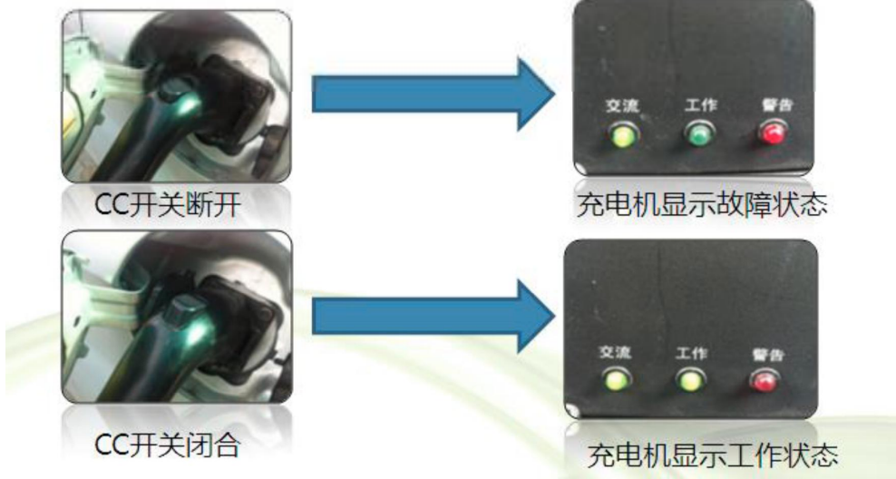
Power indicator light, when connected to AC power, the power indicator light will light up
Work
When the charger is connected to the battery and enters the charging state, the charging indicator light turns on.
warn
Warning indicator light, lights up when there is a fault inside the charger or an incorrect operation
| Fault description | Workaround |
| Not charging, the power AC light is off | Check whether the high-voltage charging bus is well connected to the charger DC output and confirm that the battery contactor is closed. |
| Not charging, warning light flashes | Confirm that the input voltage is between 170VAC and 263VAC. The cross-sectional area of the input cable is above 2.5mm². |
| Not charging, warning light flashes, and fan does not turn | Overheat warning, please clean the dust on the fan |
4. Vehicle charger fault signal:
The fault information of the on-board charger will be reported to the bus through the CAN bus, and the fault information can be found through the CAN bus.
Common faults:
1. 12V low voltage power supply is abnormal. When the 12V module of the charger is abnormal, the BMS, instrument, etc. cannot communicate with the charger because there is no wake-up signal.
Judgment method: When 12V is not powered, the easiest way to judge is that when AC power is on, the battery does not make a relay closing sound, which is generally 12V abnormal. It is necessary to check the charging wake-up fuse and relay in the low-voltage fuse box, and whether the charger terminal has a pin withdrawal situation.
2. The battery voltage detected by the charger does not meet the requirements. This problem occurs when the BMS can work normally during the charging process, but the charger needs to detect the power battery voltage before it starts working. When the power battery voltage is within the working range, the on-board charger can work normally, otherwise the charger thinks that the battery does not meet the charging requirements.
Judgment method: This situation is usually caused by the high-voltage plug-in terminal being pulled out or the high-voltage fuse being blown, or the battery voltage exceeding the operating range.
3. The handshake between the charger and the charging pile is abnormal. During the operation of the charger, the charger will detect the handshake signal between the charger and the charging pile. When it is determined that the CC switch is disconnected, the charger thinks that the charging gun is about to be unplugged, and it will stop working to prevent live plugging and unplugging, thereby increasing the life of the charging gun terminal.
Previous article:Application of CANOPEN bus encoder in vehicle technology
Next article:HMI_Board_LVGL displays vehicle speed and engine speed based on the CAN built into the development board
- Huawei's Strategic Department Director Gai Gang: The cumulative installed base of open source Euler operating system exceeds 10 million sets
- Analysis of the application of several common contact parts in high-voltage connectors of new energy vehicles
- Wiring harness durability test and contact voltage drop test method
- Sn-doped CuO nanostructure-based ethanol gas sensor for real-time drunk driving detection in vehicles
- Design considerations for automotive battery wiring harness
- Do you know all the various motors commonly used in automotive electronics?
- What are the functions of the Internet of Vehicles? What are the uses and benefits of the Internet of Vehicles?
- Power Inverter - A critical safety system for electric vehicles
- Analysis of the information security mechanism of AUTOSAR, the automotive embedded software framework
 Professor at Beihang University, dedicated to promoting microcontrollers and embedded systems for over 20 years.
- Innolux's intelligent steer-by-wire solution makes cars smarter and safer
- 8051 MCU - Parity Check
- How to efficiently balance the sensitivity of tactile sensing interfaces
- What should I do if the servo motor shakes? What causes the servo motor to shake quickly?
- 【Brushless Motor】Analysis of three-phase BLDC motor and sharing of two popular development boards
- Midea Industrial Technology's subsidiaries Clou Electronics and Hekang New Energy jointly appeared at the Munich Battery Energy Storage Exhibition and Solar Energy Exhibition
- Guoxin Sichen | Application of ferroelectric memory PB85RS2MC in power battery management, with a capacity of 2M
- Analysis of common faults of frequency converter
- In a head-on competition with Qualcomm, what kind of cockpit products has Intel come up with?
- Dalian Rongke's all-vanadium liquid flow battery energy storage equipment industrialization project has entered the sprint stage before production
- Allegro MicroSystems Introduces Advanced Magnetic and Inductive Position Sensing Solutions at Electronica 2024
- Car key in the left hand, liveness detection radar in the right hand, UWB is imperative for cars!
- After a decade of rapid development, domestic CIS has entered the market
- Aegis Dagger Battery + Thor EM-i Super Hybrid, Geely New Energy has thrown out two "king bombs"
- A brief discussion on functional safety - fault, error, and failure
- In the smart car 2.0 cycle, these core industry chains are facing major opportunities!
- The United States and Japan are developing new batteries. CATL faces challenges? How should China's new energy battery industry respond?
- Murata launches high-precision 6-axis inertial sensor for automobiles
- Ford patents pre-charge alarm to help save costs and respond to emergencies
- New real-time microcontroller system from Texas Instruments enables smarter processing in automotive and industrial applications
- 【IoT Smart Home System】---Temperature and humidity data collection and upload (1)
- Zhang Chaoyang questioned 5G: Such high-frequency electromagnetic waves are very harmful to the human body
- Design of a small dual-band RF energy receiving antenna
- What are the definitions of linear power supply, switching power supply, and thyristor power supply? What are their differences? What are their applications? What are their advantages and disadvantages?
- Goodbye 2019, hello 2020! Year-end summary and New Year's plan
- Sixth finger
- What exactly is UWB technology?
- [NXP Rapid IoT Review] Rapid IoT Studio Simple Programming Step 3 Bluetooth Connection Control Test
- 【GD32L233C-START Review】New Construction
- 【AT-START-F403A Review】II. Exploration of Simulated Virtual Serial Port

 Design considerations for clamping network very high voltage monolithic off-line PWM controller


 京公网安备 11010802033920号