1 Three-phase short circuit in infinite power supply system
First, the system diagram of the infinite power supply system is given, as shown in the figure below. A three-phase short circuit occurs at 0.02s, and the corresponding line parameters are shown in Figure 2. The amplitude of the short-circuit current periodic component and the magnitude of the impact current are obtained by Simulink simulation.

Figure 1 Infinite power supply system diagram

Figure 2 Line parameters
Then, we perform theoretical calculations in order to compare with the simulation results. The process of theoretical calculations is as follows:
First, define the benchmark value: SB=100MVA, UB=110kV (take the high voltage side).
Then calculate the per-unit reactance of each component:
XL=0.450*SB/UB2;
XT=(Uk%/100)(SB/SN);
X*∑= XL+ XT;
Then calculate the per-unit value and actual amplitude of the effective value of the short-circuit period component
Iw=1/ X∑;
Iw= IwIB= I*w *sqrt(2)*100/(sqrt(3)*11)=13.70kA;
Finally, the impulse coefficient Kimp=1.8, then the impulse current is:
Iimp=Kimp*Iw=1.8*13.7=24.66kA。
Next, we will briefly introduce the simulation model. The complete simulation model is shown in the figure below.

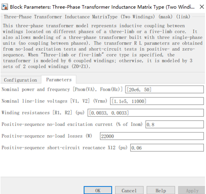
The parameters of the transformer are shown in the figure below.

Set the three-phase short-circuit trigger time to 0.02s, as shown in the figure below

Short-circuit current and other parameters are measured using VI measurement, and the corresponding parameters are shown in the figure below.

The simulation results are shown in the figure below

It can be seen from the simulation results that the impact current is between 20kA and 25kA, and the three-phase short-circuit current amplitude is around 15kA, which is basically the same as the results of theoretical calculations.
2 Transient simulation of three-phase short circuit of synchronous generator
First, the complete model diagram of Simulink simulation is given, as shown below.

The synchronous generator uses a synchronous motor module, and the corresponding module settings are shown in the figure below.

The parameter settings of the step-up transformer are shown in the figure below.

When it is set to 0.08s, a three-phase short circuit occurs, as shown in the figure below.

The three-phase stator current in the final simulation results is shown in the figure below.

Previous article:A brief discussion on key technical requirements of motor manufacturing process
Next article:How to build high-channel-density digital IO modules for next-generation industrial automation controllers
- Popular Resources
- Popular amplifiers
- Huawei's Strategic Department Director Gai Gang: The cumulative installed base of open source Euler operating system exceeds 10 million sets
- Analysis of the application of several common contact parts in high-voltage connectors of new energy vehicles
- Wiring harness durability test and contact voltage drop test method
- Sn-doped CuO nanostructure-based ethanol gas sensor for real-time drunk driving detection in vehicles
- Design considerations for automotive battery wiring harness
- Do you know all the various motors commonly used in automotive electronics?
- What are the functions of the Internet of Vehicles? What are the uses and benefits of the Internet of Vehicles?
- Power Inverter - A critical safety system for electric vehicles
- Analysis of the information security mechanism of AUTOSAR, the automotive embedded software framework
 Professor at Beihang University, dedicated to promoting microcontrollers and embedded systems for over 20 years.
- Innolux's intelligent steer-by-wire solution makes cars smarter and safer
- 8051 MCU - Parity Check
- How to efficiently balance the sensitivity of tactile sensing interfaces
- What should I do if the servo motor shakes? What causes the servo motor to shake quickly?
- 【Brushless Motor】Analysis of three-phase BLDC motor and sharing of two popular development boards
- Midea Industrial Technology's subsidiaries Clou Electronics and Hekang New Energy jointly appeared at the Munich Battery Energy Storage Exhibition and Solar Energy Exhibition
- Guoxin Sichen | Application of ferroelectric memory PB85RS2MC in power battery management, with a capacity of 2M
- Analysis of common faults of frequency converter
- In a head-on competition with Qualcomm, what kind of cockpit products has Intel come up with?
- Dalian Rongke's all-vanadium liquid flow battery energy storage equipment industrialization project has entered the sprint stage before production
- Allegro MicroSystems Introduces Advanced Magnetic and Inductive Position Sensing Solutions at Electronica 2024
- Car key in the left hand, liveness detection radar in the right hand, UWB is imperative for cars!
- After a decade of rapid development, domestic CIS has entered the market
- Aegis Dagger Battery + Thor EM-i Super Hybrid, Geely New Energy has thrown out two "king bombs"
- A brief discussion on functional safety - fault, error, and failure
- In the smart car 2.0 cycle, these core industry chains are facing major opportunities!
- The United States and Japan are developing new batteries. CATL faces challenges? How should China's new energy battery industry respond?
- Murata launches high-precision 6-axis inertial sensor for automobiles
- Ford patents pre-charge alarm to help save costs and respond to emergencies
- New real-time microcontroller system from Texas Instruments enables smarter processing in automotive and industrial applications
- Solution to inaccurate AD sampling
- What is the A4G three-pin tube in the KA3842 switching power supply circuit?
- Made a TikTok-like APP that supports album video sliding carousel, now open source
- MSP430 clock setting and application
- MSP430F5438 Timer Summary
- [Shanghai Hangxin ACM32F070 development board + touch function evaluation board] Development environment construction and initial experience
- 520, Give Tang Monk a Wife
- Talk about differential signal
- DSP code optimization instructions in CCS
- Help, what kind of lights are these? I see them for the first time.

 A_2.89_uW_Dry-Electrode_Enabled_Clockless_Wireless_ECG_SoC_for_Wearable_Applications


 京公网安备 11010802033920号