The load current of a relay is larger than that of a transistor, but the output frequency cannot be too fast due to the influence of the mechanical device, and there is also a limit on the mechanical life. The load current of a transistor is smaller than that of a relay, but the output frequency is fast and can be used for high-speed pulse output without any limit on the mechanical life.
1. S7-200 SMART digital I/O wiring diagram
Different CPU models input/output wiring
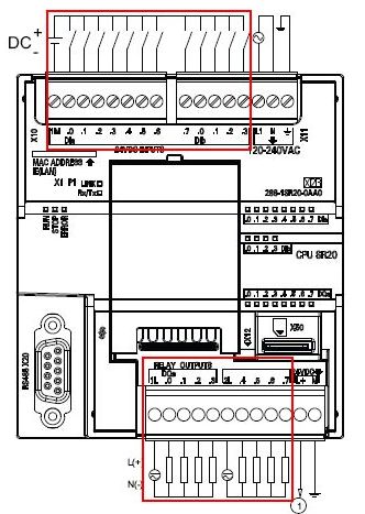
Figure 1. CPU SR20 wiring diagram
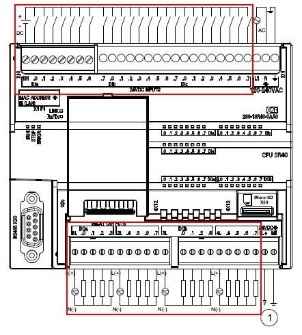
Figure 2. CPU SR40 wiring diagram
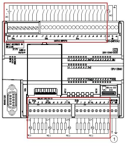
Figure 3. CPU CR40 wiring diagram
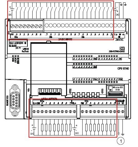
Figure 4. CPU ST40 wiring diagram
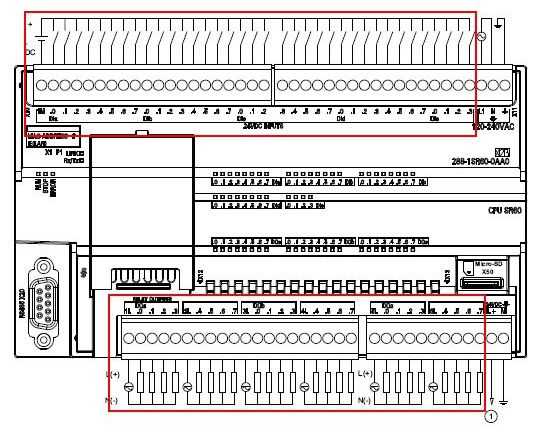
Figure 5. CPU SR60 wiring diagram
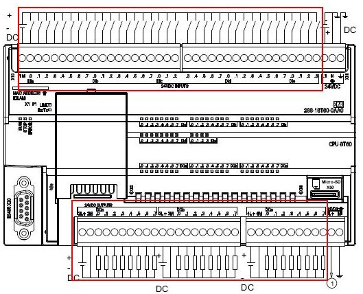
Figure 6. CPU ST60 wiring diagram
Digital input wiring
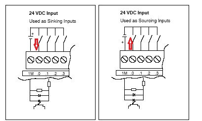
Figure 7. Sink input connection Figure 8. Source input connection
For most inputs, they are 24VDC inputs, among which I0.0-I0.3 of ST CPU supports 5-24V input, and I0.6 and I0.7 of ST20/30 also support 5-24V input. As shown in the following table:

The digital input points of S7-200 SMART are bidirectional diodes inside, which can be connected as a sink type (Figure 7) or a source type (Figure 8), as long as each group is connected the same.
For digital input circuits, the key is to form a current loop. Input points can be connected to different power supplies in groups, or these power supplies can have no connection with each other.
Digital output wiring
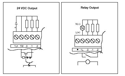
Figure 9. Source output Figure 10. Relay output
The transistor output can only be connected as a source output (Figure 9), not as a sink output, that is, the output is 24V.
The relay output is a group of dry nodes sharing a common terminal, which can be connected to AC or DC, with a voltage level up to 220V.
For example: 24V/110V/220V AC/DC signals can be connected. But it is necessary to ensure that a group of outputs are connected to the same voltage (a group shares a common terminal, such as 1L, 2L). For weak signals, such as signals less than 5V, you need to verify the reliability of its output yourself. When the relay output point (Figure 10) is connected to a DC power supply, the common terminal can be connected to either positive or negative.
For digital output circuits, the key is to form a current loop. The output points can be connected to different power supplies in groups, and these power supplies can have no connection with each other.
1 represents 24VDC sensor power output
FAQ
1. Can the digital input terminal of the same module be connected to devices with both NPN and PNP signals at the same time?
No, because the current directions of the two types of signals, NPN and PNP, are opposite to each other in the loop formed at the DI terminal. Similarly, the current directions at the M point are also opposite, as shown in Figures 7 and 8, where the current directions of the NPN and PNP loops are different. If the two signals are connected to one M terminal, there will be two current directions at the M terminal, which is incorrect. Therefore, devices with NPN and PNP signals cannot be connected to the DI input terminal of the same module at the same time.
2. DO is divided into two types: transistor and relay. What is the difference between them?
The load current of a relay is larger than that of a transistor, but the output frequency cannot be too fast due to the influence of the mechanical device, and there is also a limit on the mechanical life. The load current of a transistor is smaller than that of a relay, but the output frequency is fast and can be used for high-speed pulse output without any limit on the mechanical life.
3. Can the digital output of S7-200 SMART CPU be connected to a sink-type device?
No, the DO terminals of the S7-200 SMART CPU and expansion modules can only be connected to source 24V devices, that is, open collector PNP devices.
4. Why does the DIAG indicator on the S7-200 SMART I/O expansion module flash red?
The main reason why the DIAG indicator of the digital expansion module flashes red is the lack of 24V DC power supply. It is recommended to check the CPU information to confirm the specific cause of the error. For how to check the CPU information, see Hardware Diagnosis or Diagnosis Method Examples.
When the I/O expansion module lacks 24V DC power supply, all channel indicators also flash red. It is recommended to check the module wiring diagram, especially the module power supply end with two rows of terminals, to determine whether the power supply wiring is correct. Taking EM DR32 as an example, the correct wiring method is shown in the figure below.
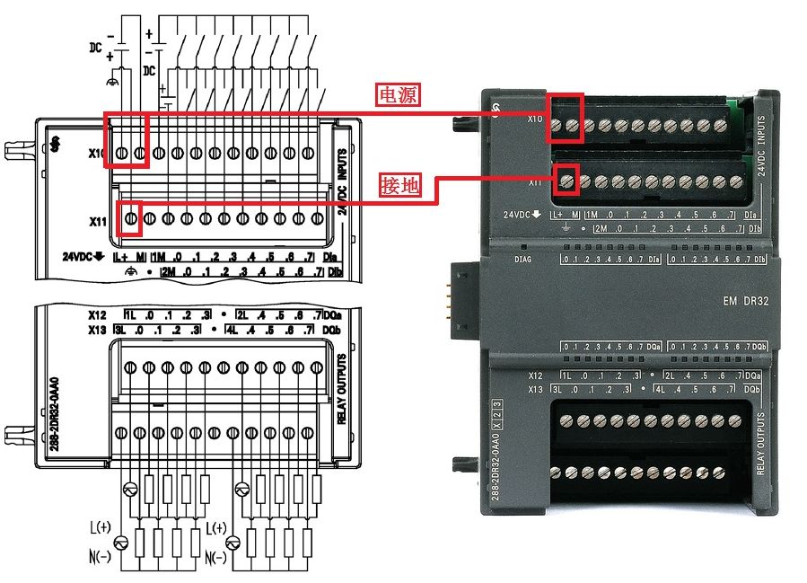
Figure 11. EM DR32 wiring diagram
Typical suppression circuit for S7-200 SMART switch output
When the S7-200 SMART switch output drives an inductive load, a suppression circuit is required. The suppression circuit can limit the rise in inductive voltage when the switch output is disconnected, protect the output, and prevent the high voltage generated when the inductive load is disconnected from causing CPU damage or CPU internal firmware errors.
In addition, the suppression circuit can limit the electrical noise generated when turning off inductive loads. An external suppression circuit connected across the load and located close to the load is most effective in reducing electrical noise.
The internal circuit of the S7-200 SMART transistor output already includes a suppression circuit that is sufficient to meet the requirements of inductive loads in most applications.
The relay output contacts are not internally protected because they can be used with either DC or AC loads.
NOTE: The effectiveness of a given suppression circuit is application specific and must be verified for your specific application.
Typical suppression circuits for transistor or relay outputs switching DC inductive loads are shown in Table 1:

The typical suppression circuit for relay outputs switching AC inductive loads is shown in Table 2:

2. S7-200 SMART analog module wiring diagram
1. Ordinary analog module wiring
There are three types of analog modules: ordinary analog modules, RTD modules and TC modules.
Ordinary analog modules can collect standard current and voltage signals. Among them, current includes two signals: 0-20mA and 4-20mA, and voltage includes three signals: +/-2.5V, +/-5V, and +/-10V.
Note: The value range of the common analog channel of S7-200 SMART CPU is 0~27648 or -27648~27648.
The wiring terminals of common analog modules are distributed as shown in Figure 1 Analog module wiring. Each analog channel has two wiring terminals.
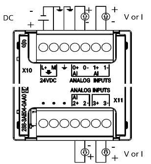
Figure 1 Analog module wiring
Analog current and voltage signals are divided into three types: four-wire, three-wire, and two-wire according to the number of analog instruments or equipment cables. Different types of signals have different wiring methods.
Four-wire signal means that the signal line and power line on the analog instrument or device add up to 4 lines. The instrument or device has a separate power supply, two power lines and two signal lines. The wiring method of the four-wire signal is shown in Figure 2 Analog voltage/current four-wire wiring.
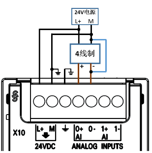
Figure 2 Analog voltage/current four-wire wiring
Three-wire signal means that the signal line and power line on the instrument or equipment add up to three lines, and the negative signal line and the power supply M line are common lines. The wiring method of the three-wire signal is shown in Figure 3 Analog voltage/current three-wire wiring.
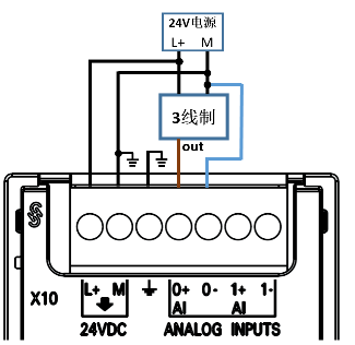
Figure 3 Analog voltage/current three-wire wiring
Two-wire signal means that the signal line and power line on the instrument or device only have two terminals. Since the S7-200 SMART CPU analog module channel does not have a power supply function, the instrument or device needs an external 24V DC power supply. The wiring method of the two-wire signal is shown in Figure 4 Analog voltage/current two-wire wiring.
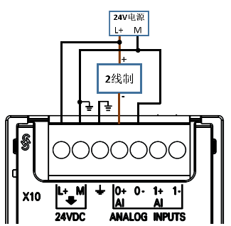
Figure 4 Analog voltage/current two-wire wiring
For unused analog channels, the two signal terminals of the channel should be short-circuited. The wiring method is shown in Figure 5. Unused channels need to be short-circuited.
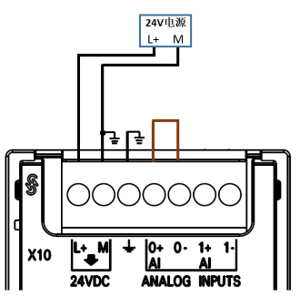
Figure 5 Unused channels need to be short-circuited
2. RTD module wiring
RTD thermal resistor temperature sensors are divided into two-wire, three-wire and four-wire types, among which the temperature measurement value of the four-wire sensor is the most accurate. The S7-200 SMART EM RTD module supports two-wire, three-wire and four-wire RTD sensor signals, and can measure common RTD temperature sensors such as PT100, PT1000, Ni100, Ni1000, Cu100, etc. For specific models, please refer to the "S7-200 SMART System Manual".
The S7-200 SMART EM RTD module can also detect resistance signals. Resistance also has two-wire, three-wire and four-wire types.
The wiring method of the EM RTD module is shown in Figure 6 Sensor RTD/Resistance Signal Wiring.
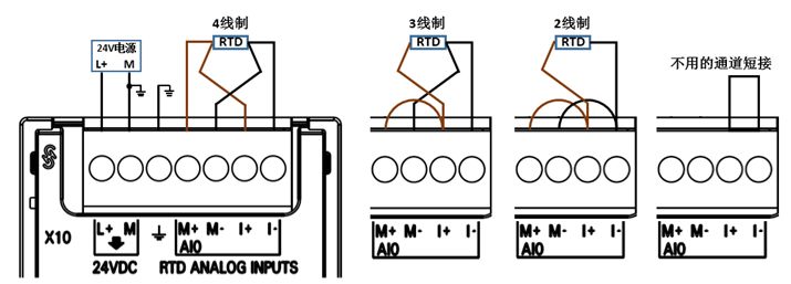
Figure 6 RTD sensor/resistance signal wiring
3. TC module wiring
The basic principle of thermocouple temperature measurement is: two conductors of different materials form a closed loop. When there is a temperature gradient at both ends, current will flow through the loop, and an electromotive force will exist between the two ends.
The S7-200 SMART EM TC module can measure J, K, T, E, R&S and N-type thermocouple temperature sensors. For specific models, please refer to the S7-200 SMART System Manual. For the wiring instructions of the TC module, refer to Figure 7 TC signal wiring.
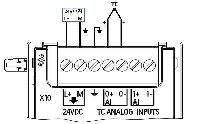
Figure 7 TC signal wiring
Note: For the wiring diagram of each module, please refer to the "Technical Specifications" chapter in the "S7-200 SMART System Manual".
Analog Frequently Asked Questions
1. Can the S7-200 SMART ordinary analog module connect to 4-20mA signals?
Yes, the S7-200 SMART CPU analog module can detect standard current signals of 0-20mA and 4-20mA. The wiring of the two current signals and the parameter settings in the STEP 7-Micro/WIN SMART software are the same. The difference is that the channel value range corresponding to 0-20mA is 0-27648, while the channel value range corresponding to 4-20mA is 5530-27648.
Previous article:You can only be considered an expert if you understand these 7 electrical diagrams of the forward and reverse control circuits of three-phase asynchronous motors.
Next article:Mitsubishi positioning module QD75 positioning control operation steps
Recommended ReadingLatest update time:2024-11-16 09:31


- Popular Resources
- Popular amplifiers
- Huawei's Strategic Department Director Gai Gang: The cumulative installed base of open source Euler operating system exceeds 10 million sets
- Analysis of the application of several common contact parts in high-voltage connectors of new energy vehicles
- Wiring harness durability test and contact voltage drop test method
- Sn-doped CuO nanostructure-based ethanol gas sensor for real-time drunk driving detection in vehicles
- Design considerations for automotive battery wiring harness
- Do you know all the various motors commonly used in automotive electronics?
- What are the functions of the Internet of Vehicles? What are the uses and benefits of the Internet of Vehicles?
- Power Inverter - A critical safety system for electric vehicles
- Analysis of the information security mechanism of AUTOSAR, the automotive embedded software framework
 Professor at Beihang University, dedicated to promoting microcontrollers and embedded systems for over 20 years.
- Innolux's intelligent steer-by-wire solution makes cars smarter and safer
- 8051 MCU - Parity Check
- How to efficiently balance the sensitivity of tactile sensing interfaces
- What should I do if the servo motor shakes? What causes the servo motor to shake quickly?
- 【Brushless Motor】Analysis of three-phase BLDC motor and sharing of two popular development boards
- Midea Industrial Technology's subsidiaries Clou Electronics and Hekang New Energy jointly appeared at the Munich Battery Energy Storage Exhibition and Solar Energy Exhibition
- Guoxin Sichen | Application of ferroelectric memory PB85RS2MC in power battery management, with a capacity of 2M
- Analysis of common faults of frequency converter
- In a head-on competition with Qualcomm, what kind of cockpit products has Intel come up with?
- Dalian Rongke's all-vanadium liquid flow battery energy storage equipment industrialization project has entered the sprint stage before production
- Allegro MicroSystems Introduces Advanced Magnetic and Inductive Position Sensing Solutions at Electronica 2024
- Car key in the left hand, liveness detection radar in the right hand, UWB is imperative for cars!
- After a decade of rapid development, domestic CIS has entered the market
- Aegis Dagger Battery + Thor EM-i Super Hybrid, Geely New Energy has thrown out two "king bombs"
- A brief discussion on functional safety - fault, error, and failure
- In the smart car 2.0 cycle, these core industry chains are facing major opportunities!
- The United States and Japan are developing new batteries. CATL faces challenges? How should China's new energy battery industry respond?
- Murata launches high-precision 6-axis inertial sensor for automobiles
- Ford patents pre-charge alarm to help save costs and respond to emergencies
- New real-time microcontroller system from Texas Instruments enables smarter processing in automotive and industrial applications
- [Problem Feedback] Anlu TangDynasty constraint file and code formatting issues
- MSP430F5529 program arrangement (serial port, AD, timer, etc.)
- Allwinner V5 Review——by IC Crawler
- 【DFRobot wireless communication module】-Gravity A6 GPRS module inspection
- MicroPython Hands-on (11) - Building the IDE environment for the control board
- [Blood Oximeter] Disassembly Part 2: Introduction to the accessories
- What should we talk about when we talk about Tesla incident
- How to Improve Heat Dissipation Using PCB Design
- Why don't all Android phones use Type-C ports?
- Live Registration | Building a Sensor-Based Test System Using CompactDAQ and LabVIEW


 Siemens PLC Programming Technology and Application Cases (Edited by Liu Zhenquan, Wang Hanzhi, Yang Kun, etc.)


 京公网安备 11010802033920号