Preface
With the vigorous promotion of new energy vehicles, the demand for functional safety is becoming increasingly strong: for electronic control systems, when a failure that violates torque safety occurs, the controller needs to enter a safe state. For permanent magnet synchronous motor drive systems, their safety states are generally either off or active short circuit (ASC).
Because permanent magnet synchronous motors have back electromotive force, if they are turned off at high speed, they may generate large power generation torque, which will violate the safety goal. Therefore, active short circuit is designed as a safety state at high speed. The so-called active short circuit is a method of actively short-circuiting the three-phase lines of the motor. After the active short circuit enters the steady state, the output torque of the permanent magnet synchronous motor in the medium and high speed area is about 0 torque, which meets the torque safety requirements.
Today, I, an electronic control novice, will talk to you about the changes in dynamic current when the motor directly enters active short circuit.
Brief Analysis of Steady-State Current of High-Speed ASC
Let's first briefly analyze the problem current situation of the permanent magnet synchronous motor after entering the ASC at high speed. In order to analyze this problem, the electronic control novice has to use the DQ axis voltage equation of the permanent magnet synchronous motor that he can never do without:

To analyze the steady-state current, the steady-state equation is simplified to:

Active short circuit is to short-circuit the three-phase lines of the motor, so ud and uq are both 0, and the steady-state current can be derived:

It can be seen from the expression that the D-axis steady-state current is less than 0, and the Q-axis steady-state current has an opposite sign to the speed; when the motor runs in the medium and high speed area, the DQ-axis inductive reactance will be much larger than Rs, and the Q-axis current will be approximately 0, so the motor works in a low-power (high-speed and low-torque) power generation state.
It is easy to understand why the motor must be in a small torque generating state: the three-phase lines of the motor are short-circuited, and the motor cannot exchange energy with the DC end. However, as long as there is current in the three phases of the motor, there will inevitably be energy consumption (copper loss and iron loss). This part of energy can only be converted from external kinetic energy. Therefore, the motor must be in a generating state, and the generated power will not be too large (the generated power must be equal to the motor's power loss).
Ignoring the Rs related terms, the approximate current expression is obtained:
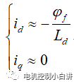
Therefore, for high-speed ASC, the steady-state current of the permanent magnet synchronous motor is actually approximately equal to the motor characteristic current i0.
Dynamic current analysis of ASC in electric state
Next, we continue to analyze the dynamic process of the motor after entering ASC:
For the convenience of analysis, let's first define the working state: forward, electric working condition, id>i0
When the motor enters ASC from normal working state, the motor terminal voltage becomes 0:
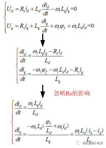
From the above expression, we can see that when iq>0, id increases; when iq<0, id decreases. When id>i0, iq decreases; when id
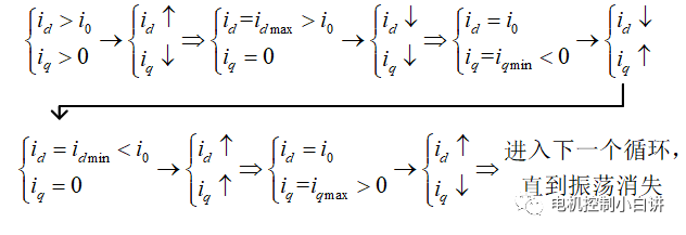
In order to verify whether the previous troublesome dynamic analysis is correct, the electronic control novice uses the Matlab simulation model for simulation (please forgive the limited resources of the electronic control novice, and there is no way to use the real bench test data). Here is the simulation waveform:
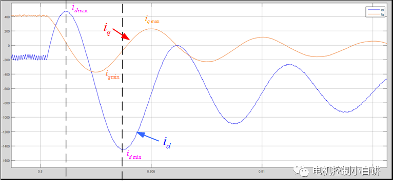
It can be seen from the above waveform that the dynamic change process of the DQ axis current is basically consistent with the previous analysis of the electronic control novice, which shows that the previous analysis method is correct (fortunately, it is consistent, otherwise it would be a slap in the face).
We can also draw the following conclusions from the waveform:
1. When the motor directly enters ASC from normal operation, a large current shock may be generated. The shock current is mainly caused by the D-axis current. At the same time, the current shock occurs a little before the motor switches from the power generation state to the electric state;
2. The impact amplitude of the D-axis current may be much larger than the steady-state current (the D-axis current impact in the simulation waveform reaches 1450A);
3. Cutting into ASC will cause the DQ axis current to oscillate;
4. The current oscillation amplitude caused by ASC will gradually decay, and the current will eventually converge to the steady-state current value. The waveform of the DQ axis current is an oscillating current with a gradually decaying amplitude superimposed on the steady-state value.
5. The oscillating component in the Q-axis current leads the oscillating component in the D-axis current by about 90° (less than 90°) in phase.
Tips:
1. Simulation working conditions: The motor runs at a frequency of 200Hz. Before entering ASC, the motor Id=-200A, Iq=400A, and the high-speed active short-circuit steady-state Id is about -600A.
2. The oscillation frequency of the DQ axis current is the same as the electrical frequency of the motor, both of which are 200Hz;
3. Why is the impact current mainly formed by the D-axis current: Because the DQ-axis current is an orthogonal current, the amplitude of the current vector is the square sum of the DQ-axis current. At the same time, when the D-axis current reaches its peak value, the Q-axis current is approximately 0, so the influence of the Q-axis current on the current amplitude can be ignored.
4. Why does the maximum value of the D-axis current not correspond to the moment when the Q-axis current is 0 in the previous analysis? This is because the influence of the stator resistance Rs was ignored in the previous analysis. If the influence of Rs is introduced, the analysis result will correspond to the waveform. I will not explain this to you here. Interested readers can analyze it by themselves.
5. Why does the oscillating component in the current gradually decay to 0: Because of the existence of stator resistance, the stator resistance will consume the energy of the oscillation and make the current gradually converge; this problem can also be understood from another perspective. The resistance and inductance form a first-order low-pass filter, which has an attenuation effect on the AC quantity, so the AC component will eventually be attenuated to 0;
6. Why does the maximum impact current amplitude appear just before the motor transitions from power generation to electric motoring? This problem can be understood from the perspective of energy. The larger the DQ axis current, the more energy stored in the corresponding motor inductance. After the motor enters the ASC state, the energy can only interact with mechanical energy. The electric state converts the inductor magnetic field energy into mechanical energy, and the inductor current decreases. Power generation converts mechanical energy into inductor magnetic field energy, and the inductor current increases. Therefore, the current amplitude in the power generation state must be greater than that in the electric state. At the same time, the motor itself has losses (copper loss and iron loss). Therefore, when the power generation power is equal to the motor's own losses, the inductor energy reaches the maximum, and the corresponding current reaches the maximum.
Dynamic current analysis of ASC in power generation state
The previous analysis shows the dynamic current change process when the electric state enters the ASC. Let's continue to analyze the dynamic current change process when switching from the power generation state to the ASC, still using the previous formula:

The electronic control novice also uses simulation to verify whether the analysis is correct:

It can be seen from the above waveform that the dynamic change process of the DQ axis current is basically consistent with the previous analysis of the electronic control novice, which shows that the previous analysis method is correct.
From the waveform we can also get the same conclusion as the electric working condition. I, an electronic control novice, will not go into details here and waste your precious time.
Comparing the waveforms of electric and power generation, it is not difficult to find that the electric state will eventually enter the same current change process as power generation. Compared with the power generation state, the electric state only adds a previous transition process to power generation, but it has no effect on the operating point where the maximum impact current occurs.
Amplitude relationship of dynamic current oscillation components of DQ axis
Let's first analyze the amplitude relationship of the DQ axis oscillation components and define the variables that need to be used in the analysis to prevent you from not knowing what I am talking about later.
i0—motor characteristic current
idm—D-axis current oscillation component amplitude
iqm—Q-axis current oscillation component amplitude
Based on the previous analysis, both electric and power generation will eventually enter the power generation condition, so here we directly analyze the power generation condition. At the same time, in order to simplify the analysis, we will not consider the attenuation effect of resistance on oscillation, that is, we assume that the oscillation amplitude is constant:
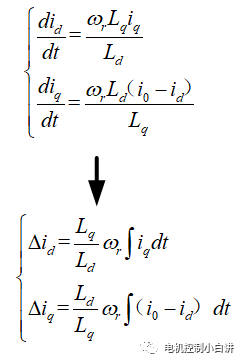
Use the formula used in the previous analysis of the dynamic change of current to make appropriate changes:
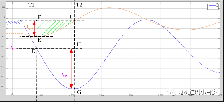
The waveform between T1 and T2 in the above waveform corresponds to a quarter of the DQ axis oscillation component; therefore, the change in the D axis current from T1 to T2 is exactly the amplitude Idm of the resonant component; at the same time, the definite integral value of iq from T1 to T2 is the green shaded area in the figure. Here, the definite integral formula can be used to calculate the integral value of iq:
Previous article:Desuo explains the requirements of automobiles for high-voltage wiring harnesses
Next article:Why should automotive chips meet functional safety requirements?
- Popular Resources
- Popular amplifiers
- Huawei's Strategic Department Director Gai Gang: The cumulative installed base of open source Euler operating system exceeds 10 million sets
- Analysis of the application of several common contact parts in high-voltage connectors of new energy vehicles
- Wiring harness durability test and contact voltage drop test method
- Sn-doped CuO nanostructure-based ethanol gas sensor for real-time drunk driving detection in vehicles
- Design considerations for automotive battery wiring harness
- Do you know all the various motors commonly used in automotive electronics?
- What are the functions of the Internet of Vehicles? What are the uses and benefits of the Internet of Vehicles?
- Power Inverter - A critical safety system for electric vehicles
- Analysis of the information security mechanism of AUTOSAR, the automotive embedded software framework
 Professor at Beihang University, dedicated to promoting microcontrollers and embedded systems for over 20 years.
- Innolux's intelligent steer-by-wire solution makes cars smarter and safer
- 8051 MCU - Parity Check
- How to efficiently balance the sensitivity of tactile sensing interfaces
- What should I do if the servo motor shakes? What causes the servo motor to shake quickly?
- 【Brushless Motor】Analysis of three-phase BLDC motor and sharing of two popular development boards
- Midea Industrial Technology's subsidiaries Clou Electronics and Hekang New Energy jointly appeared at the Munich Battery Energy Storage Exhibition and Solar Energy Exhibition
- Guoxin Sichen | Application of ferroelectric memory PB85RS2MC in power battery management, with a capacity of 2M
- Analysis of common faults of frequency converter
- In a head-on competition with Qualcomm, what kind of cockpit products has Intel come up with?
- Dalian Rongke's all-vanadium liquid flow battery energy storage equipment industrialization project has entered the sprint stage before production
- Allegro MicroSystems Introduces Advanced Magnetic and Inductive Position Sensing Solutions at Electronica 2024
- Car key in the left hand, liveness detection radar in the right hand, UWB is imperative for cars!
- After a decade of rapid development, domestic CIS has entered the market
- Aegis Dagger Battery + Thor EM-i Super Hybrid, Geely New Energy has thrown out two "king bombs"
- A brief discussion on functional safety - fault, error, and failure
- In the smart car 2.0 cycle, these core industry chains are facing major opportunities!
- The United States and Japan are developing new batteries. CATL faces challenges? How should China's new energy battery industry respond?
- Murata launches high-precision 6-axis inertial sensor for automobiles
- Ford patents pre-charge alarm to help save costs and respond to emergencies
- New real-time microcontroller system from Texas Instruments enables smarter processing in automotive and industrial applications
- 【Featured Q&A】About battery protection and fuel gauge design
- Analysis of 2019 National Competition Questions: Questions F, H, and K
- Security engineering contractors are still using the traditional old method to quote. Come in and see if this works!
- [New ways to play with SAMR21] 14. LSM6DSO gyroscope sensor
- Excuse me, are the units of magnetic field strength, Henry, and inductance, the same units? The former is A/m and the latter is ohm*second
- I want to use FPGA to make an SPI Slave. I have a few questions about the clock.
- [NXP Rapid IoT Review] + First Look at IOT Kit
- Overseas battery giants are rushing into the lithium iron phosphate battery field - what do you think?
- 【N32G457】High-end Rubik's Cube based on RT-Thread and N32G457
- Revealed! PPO, the "hard core" material in the 5G era


 Motor Control and Learning (Markus Latash, Francis Lestienne)
 Unmanned Toy Car Collaborative Tracking - Dual Cars! Start + Ultrasonic Distance Measurement


 京公网安备 11010802033920号