We know that switch Hall sensors are often used in some small controllers with low precision requirements, relatively simple working conditions and low cost due to their own characteristics.
As for large motors used in cars, the most commonly used position sensors are resolvers (rotators). So, here is a detailed introduction to resolvers:
Working Principle of Resolver
The generation of incentives
Resolver Calibration
Working Principle of Resolver
A resolver (resolver) is a position sensor commonly used in motor control. It is used to reflect the rotor position of the motor and provide it to the software for motor control and other related algorithms.
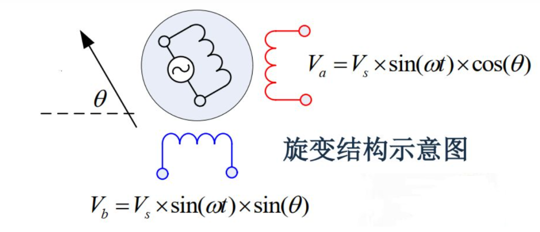
As shown in the figure above, the resolver can also be understood as a small motor, which is also divided into a stator and a rotor. Usually the rotor of the resolver is installed on the shaft of the motor, rotates synchronously with the motor, and senses position information in the stator coil, which is transmitted by the stator coil to obtain the final position.

The structural diagram of the resolver is shown in the figure above. The middle R1R2 coil is the rotor coil, S1S2, S3S4 are the stator coils perpendicular to each other. When a high-frequency sinusoidal signal is passed through R1R2, we usually call this signal an excitation signal; at this time, a high-frequency induction signal will be induced in the secondary coil, and this signal contains an envelope signal with position information; we extract the envelope of the returned induction signal to obtain the corresponding sine and cosine information; after decoding by hard decoding/soft decoding, we can get the absolute position information of the stator (note that it is the absolute position here). Let's deduce this process:
Assume the excitation signal is:
Vα=Vs∗sin(ωt)
As shown in the above figure, the angle between the excitation coil of the resolver and the horizontal is θ. Then, combined with the signal in the excitation coil, the signals in the two induction coils can be obtained respectively:
Va=Vs∗sin(ωt)∗cos(θ)
Vb=Vs∗sin(ωt)∗sin(θ)
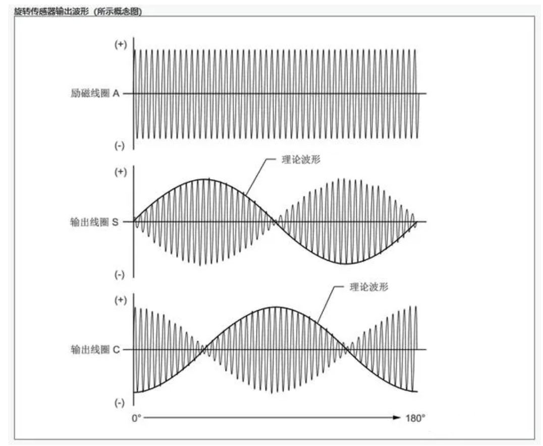
Therefore, we can get the waveforms of excitation, sine and cosine as follows:

The sine and cosine waveforms are sinusoidal curves with changing amplitudes. It is not difficult to understand from the above equations that the sine curve is actually generated by the excitation source, and the reason why the amplitude keeps changing is that the angle θ between the excitation coil and the secondary coil keeps changing during the rotation process, so this waveform is generated. The outer envelope of this waveform (the black line part in the figure) is the sine and cosine signal we need.
Therefore, during the decoding process, we only need to extract the outer envelope of the sine and cosine signals to obtain the absolute position information of the rotor.
Well, based on the above analysis, after understanding the main structure and working principle of the resolver, two very important functions of the resolver application are the generation of excitation signals and the extraction of the outer envelope and angle calculation of the recovered sine and cosine signals (this part is usually called resolver decoding).
The generation of incentives
From the previous introduction, we know that the work of resolver requires a high-frequency sinusoidal signal input, which we usually call the excitation signal. In actual application, the sinusoidal curve cannot be directly obtained through a certain module of MCU. Therefore, we can naturally think of PWM modulation technology, which is the same as motor control, through high-frequency PWM pulse width modulation, and finally achieves the effect of approximate output of sine and cosine voltage.
On the other hand, in addition to the high-frequency PWM signal output by the MCU, the controller hardware also needs to match the design of related circuits. The functions that the hardware needs to complete include adjusting the ratio, adjusting the bias, increasing the driving capability, etc. Only after the combination of software and hardware can we finally get the excitation signal waveform we need. Regarding the hardware circuit of the resolver, there are many resources available on the Internet for reference, so I will not introduce them in detail here.
In order to illustrate the generation of the excitation signal more intuitively, I roughly performed a simulation using Simulink+Pspice joint simulation.
In Simulink, a PWM waveform (pulse width change) is generated at a frequency of more than 300kHz. In PSpice, a set of excitation circuits available on the Internet is built. Finally, how the output of the circuit (that is, the excitation input to the resolver during actual application) changes is observed.

Co-simulation Model

PSpice Hardware Model
Simulation results:
Input signal, generate high frequency PWM with variable pulse width

High frequency PWM signal
The positive and negative results of the incentives generated:

Stimulus waveform
The excitation waveform obtained by simulation has some clipping at the peak point. This is because there are two relay modules where PWM is generated. When the PWM pulse width is small, the buffer setting in the relay may not be met, so the waveform is missing at the peak point.
Resolver Calibration
There are many popular terms for resolver calibration in daily work, such as zero angle calibration, motor angle calibration, etc. Although the terms are different, the content and function are the same, that is, to know the angle deviation between the zero position of the resolver and the zero position of the motor.
The reason is very simple. As we have emphasized before, resolver is an absolute position sensor that obtains the absolute position of the motor rotor. However, the essence of our motor control is the interaction between the stator magnetic field and the rotor magnetic field, and the stator magnetic field is obtained through the output current. Therefore, what we need is not the absolute position of the rotor, but the relative position between the rotor and the stator. With the relative position, the stator magnetic field can be accurately output.
The significance of resolver calibration has been explained above, and the method is also very simple. The calibration of the resolver needs to find the deviation between the resolver's zero position and the motor's zero position. Since the resolver can obtain the absolute position, in actual application, we only need to find the resolver position corresponding to the motor's zero position, which is actually the deviation between the resolver's zero position and the motor's zero position.
There are many ways to find the zero position of the motor, such as Id, UαUβ, etc. There are many ways, each with its own advantages and disadvantages, so I will not introduce them in detail.
Finally, let me add that, as mentioned at the beginning, a resolver can actually be understood as a small motor, because a resolver also has the concept of pole pairs. For convenience, we usually use a resolver with the same pole pairs as the large motor as a sensor, so that the angle decoded by the resolver is the electrical angle of the motor. If the pole pairs between the two are not equal, there is still a conversion relationship.
Previous article:Typical applications of displacement sensors in industrial production
Next article:Servo optimization principle and optimization scheme design
- Popular Resources
- Popular amplifiers
- Huawei's Strategic Department Director Gai Gang: The cumulative installed base of open source Euler operating system exceeds 10 million sets
- Analysis of the application of several common contact parts in high-voltage connectors of new energy vehicles
- Wiring harness durability test and contact voltage drop test method
- Sn-doped CuO nanostructure-based ethanol gas sensor for real-time drunk driving detection in vehicles
- Design considerations for automotive battery wiring harness
- Do you know all the various motors commonly used in automotive electronics?
- What are the functions of the Internet of Vehicles? What are the uses and benefits of the Internet of Vehicles?
- Power Inverter - A critical safety system for electric vehicles
- Analysis of the information security mechanism of AUTOSAR, the automotive embedded software framework
 Professor at Beihang University, dedicated to promoting microcontrollers and embedded systems for over 20 years.
- Innolux's intelligent steer-by-wire solution makes cars smarter and safer
- 8051 MCU - Parity Check
- How to efficiently balance the sensitivity of tactile sensing interfaces
- What should I do if the servo motor shakes? What causes the servo motor to shake quickly?
- 【Brushless Motor】Analysis of three-phase BLDC motor and sharing of two popular development boards
- Midea Industrial Technology's subsidiaries Clou Electronics and Hekang New Energy jointly appeared at the Munich Battery Energy Storage Exhibition and Solar Energy Exhibition
- Guoxin Sichen | Application of ferroelectric memory PB85RS2MC in power battery management, with a capacity of 2M
- Analysis of common faults of frequency converter
- In a head-on competition with Qualcomm, what kind of cockpit products has Intel come up with?
- Dalian Rongke's all-vanadium liquid flow battery energy storage equipment industrialization project has entered the sprint stage before production
- Allegro MicroSystems Introduces Advanced Magnetic and Inductive Position Sensing Solutions at Electronica 2024
- Car key in the left hand, liveness detection radar in the right hand, UWB is imperative for cars!
- After a decade of rapid development, domestic CIS has entered the market
- Aegis Dagger Battery + Thor EM-i Super Hybrid, Geely New Energy has thrown out two "king bombs"
- A brief discussion on functional safety - fault, error, and failure
- In the smart car 2.0 cycle, these core industry chains are facing major opportunities!
- The United States and Japan are developing new batteries. CATL faces challenges? How should China's new energy battery industry respond?
- Murata launches high-precision 6-axis inertial sensor for automobiles
- Ford patents pre-charge alarm to help save costs and respond to emergencies
- New real-time microcontroller system from Texas Instruments enables smarter processing in automotive and industrial applications
- [ESP32-Korvo Review] Part 3: Smart Voice Assistant ESP-Skainet
- Differences between MSP430 programmer emulator and JTAG, SBW, and BSL interfaces
- ESP32-S2 development pit (1) - open filling
- MSP430 timer controls PWM output
- 【Short-term weather forecast system】Basic functions of indoor devices are realized
- [GD32E503 Review] Part 6: FreeRTOS and RTC screen display
- [Synopsys IP Resources] Automotive cybersecurity starts with chips and IP
- What to do about analog switch crosstalk?
- 24-pin composite video encoder IC model required
- BMS Rapid Prototyping Platform

 Machine Vision Algorithms and Applications 2nd Edition
 AB PLC例程 [MMS_040340]AMCI 1642 2-Ch resolver interface module configuration with CompactLogix.


 京公网安备 11010802033920号