Application scenarios of electro-hydraulic servo valves
Due to its high precision and fast control capability, electro-hydraulic servo valves are widely used in the fields of aerospace and military equipment, as well as in open-loop or closed-loop electro-hydraulic control systems of various industrial equipment such as machine tools, plastics, rolling mills, and vehicles. In particular, they are widely used in situations where the system requires high dynamic response and large output power.
(1) Position control circuit of electro-hydraulic servo valve. Figure 172 shows the linear position circuit of the hydraulic cylinder controlled by the electro-hydraulic servo valve. Figure 172 (a) shows its principle diagram, and Figure 172 (b) shows its functional block diagram. When the system receives the command signal from the command potentiometer, the electro-mechanical converter of the electro-hydraulic servo valve 2 is activated. After the energy conversion is amplified by the hydraulic amplifier (pilot stage and power stage), the pressure oil of the hydraulic source is supplied to the hydraulic cylinder 3 through the electro-hydraulic servo valve to drive the load to the predetermined position. The feedback signal detected by the feedback potentiometer (position sensor) is compared with the input command signal through the servo amplifier 1, so that the actuator moves accurately to the desired position.
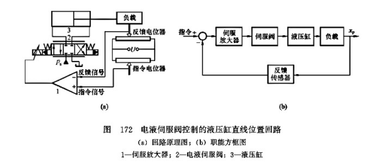
Figure 173 shows the linear position loop of the hydraulic motor controlled by the electro-hydraulic servo valve, and Figure 173 (a) shows its principle diagram, and Figure 173 (b) shows its functional block diagram. When the system inputs the command signal, it is amplified by energy conversion, and the pressure oil of the hydraulic source is supplied to the hydraulic motor 3 through the electro-hydraulic servo valve 2. The gear reducer 4 and the screw nut mechanism 5 convert the rotary motion of the motor into the linear motion of the load. The feedback signal detected by the position sensor is compared with the input command signal through the servo amplifier 1, so that the load moves accurately to the required position.
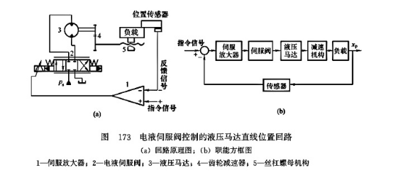
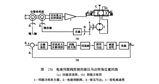
Figure 174 shows the angular position loop of the hydraulic motor controlled by the electro-hydraulic servo valve. Figure 174 (a) shows its principle diagram, and Figure 174 (b) shows its functional block diagram. It uses a self-synchronous angle unit as an angle difference measuring device (3 wires represent the lead wires of the stator winding, 2 wires represent the lead wires of the rotor winding, and the dotted line through the center of the circle represents the rotating shaft). The input shaft is connected to the transmitter shaft, and the output shaft is connected to the receiver. The self-synchronous angle unit detects the angle between the input shaft and the output shaft, and converts the angle difference into an amplitude modulated voltage signal. After amplification by the AC amplifier and demodulation by the demodulator, the AC voltage signal is converted into a DC voltage signal, which is then amplified by the servo power amplifier 1 to generate a differential current to control the electro-hydraulic servo valve 2. After the hydraulic energy is amplified, the pressure oil of the hydraulic source is supplied to the hydraulic motor 3 through the electro-hydraulic servo valve 2. The motor drives the load to rotate through the gear reducer 4. After the above feedback signal is compared with the input command signal, the load moves accurately at the required angular position.
(2) Speed control circuit of electro-hydraulic servo valve. Figure 175 shows a circuit that uses an electro-hydraulic servo valve to control the rotation speed of a bidirectional fixed hydraulic motor to maintain a certain value. Figure 175 (a) shows its principle diagram, and Figure 175 (b) shows its functional block diagram. When the system inputs a command signal, the electrical mechanical converter of the electro-hydraulic servo valve 2 is activated. After the energy conversion is amplified by the hydraulic amplifier (pilot stage and power stage), the pressure oil of the hydraulic source is supplied to the bidirectional hydraulic motor 3 through the electro-hydraulic servo valve, so that the hydraulic motor drives the load to work at a certain speed; at the same time, the detection feedback signal uf of the speed measuring motor (speed sensor) 4 is compared with the input command signal through the servo amplifier 1, and the error signal obtained controls the valve opening of the electro-hydraulic servo valve, so that the actuator speed is kept near the set value.
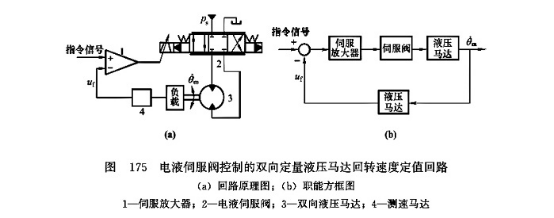
Figure 176 shows the hydraulic motor speed circuit controlled by an open-loop variable pump. Figure 176 (a) shows its principle diagram, and Figure 176 (b) shows its functional block diagram. The bidirectional variable hydraulic pump 5, the bidirectional fixed hydraulic motor 6, the safety overflow valve group 7 and the oil replenishment check valve group 8 form a closed oil circuit, and the speed of the hydraulic motor 6 is adjusted by changing the displacement of the variable pump 5. The displacement adjustment of the variable pump is achieved by the displacement adjustment of the double-rod hydraulic cylinder 3 controlled by the electro-hydraulic servo valve 2. The actuator and the load are open-loop with the hydraulic cylinder controlled by the electro-hydraulic servo valve. When the system inputs the command signal, the pressure oil of the control hydraulic source is supplied to the double-rod hydraulic cylinder 3 through the electro-hydraulic servo valve 2, so that the variable mechanism of the hydraulic cylinder driving the variable pump works at a certain position; at the same time, the detection feedback signal of the position sensor 4 is compared with the input command signal through the servo amplifier 1, and the error signal obtained controls the valve opening of the electro-hydraulic servo valve, so that the variable mechanism of the variable pump, that is, the displacement of the variable pump, is kept near the set value, and finally ensures that the hydraulic motor 6 works near the desired speed value.
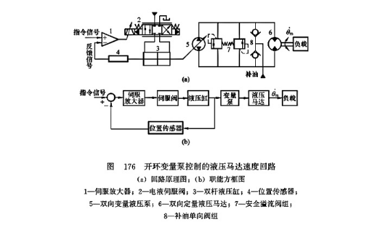
FIG177 shows a hydraulic motor speed circuit controlled by a closed-loop variable pump, FIG177 (a) shows its principle diagram, and FIG177 (b) shows its functional block diagram. The oil circuit structure is basically the same as the hydraulic motor speed circuit controlled by an open-loop variable pump shown in FIG176, except that a speed measuring motor (speed sensor) 9 is added between the load and the command mechanism to form a closed-loop speed control circuit. Therefore, its speed control accuracy is higher.

(3) Force and pressure control circuit of electro-hydraulic servo valve. Figure 178 (a) shows the force control circuit of electro-hydraulic servo valve. The oil source supplies oil to the double-rod hydraulic cylinder 3 through the electro-hydraulic servo valve 2. The force generated by the hydraulic cylinder is applied to the load. The detection feedback signal of the force sensor 4 is compared with the input command signal through the servo amplifier 1, and then the action of the cylinder is controlled by the electro-hydraulic servo valve, thereby keeping the load force basically constant. Figure 178 (b) shows the control circuit for maintaining the constant pressure difference between the two chambers of the double-rod hydraulic cylinder. When the electro-hydraulic servo valve 2 receives the input command signal and converts and amplifies the signal, the pressure difference between the two chambers of the double-rod hydraulic cylinder 3 reaches a certain set value. When the pressure in the cylinder changes, the detection feedback signal of the pressure difference sensor 5 controlled near the hydraulic cylinder is compared with the input signal command through the servo amplifier 1, and then the action of the cylinder is controlled by the electro-hydraulic servo valve, thereby keeping the pressure difference between the two chambers of the hydraulic cylinder basically constant. Figure 178 (c) shows the functional block diagram of the force and pressure control circuit of the electro-hydraulic servo valve.
(4) Hydraulic cylinder synchronization control circuit of electro-hydraulic servo valve. Figure 179 shows a hydraulic cylinder synchronization control circuit that uses an electro-hydraulic servo valve to release oil. The diverter valve 6 is used for rough synchronization control, and the electro-hydraulic servo valve 5 is used to bypass the oil release according to the feedback signal of the position error detector (differential transformer) 3 to achieve precise synchronization control. This circuit has high synchronization accuracy (up to 0.2mm) and can eliminate the position error of the two cylinders by itself; rough synchronization can still be achieved when the servo valve fails. The servo valve can use a small flow valve to release oil, but the cost is high and the efficiency is low. It is suitable for occasions where high synchronization accuracy is required.
Figure 180 shows a hydraulic cylinder synchronization control circuit using an electro-hydraulic servo valve tracking. The electro-hydraulic servo valve 1 controls the valve opening and outputs a flow rate that is the same as that of the reversing valve 2, so that the two hydraulic cylinders can achieve bidirectional synchronous motion. This circuit has high synchronization accuracy, but is relatively expensive. It is suitable for situations where the two hydraulic cylinders are far apart and require high synchronization accuracy.
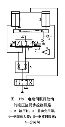
Figure 181 shows a synchronous control circuit using an electro-hydraulic servo valve to distribute flow. The electro-hydraulic servo valve 2 continuously adjusts the valve opening according to the feedback signals from displacement sensors 4 and 5, controls the input or output flow of the two hydraulic cylinders, and enables them to achieve bidirectional synchronous motion. The characteristics of this circuit are the same as those of the circuit shown in Figure 175.
Previous article:Analysis of the characteristics of solid-state transformers
Next article:Detailed explanation of the working principle of solid-state transformer
- Huawei's Strategic Department Director Gai Gang: The cumulative installed base of open source Euler operating system exceeds 10 million sets
- Analysis of the application of several common contact parts in high-voltage connectors of new energy vehicles
- Wiring harness durability test and contact voltage drop test method
- Sn-doped CuO nanostructure-based ethanol gas sensor for real-time drunk driving detection in vehicles
- Design considerations for automotive battery wiring harness
- Do you know all the various motors commonly used in automotive electronics?
- What are the functions of the Internet of Vehicles? What are the uses and benefits of the Internet of Vehicles?
- Power Inverter - A critical safety system for electric vehicles
- Analysis of the information security mechanism of AUTOSAR, the automotive embedded software framework
 Professor at Beihang University, dedicated to promoting microcontrollers and embedded systems for over 20 years.
- Innolux's intelligent steer-by-wire solution makes cars smarter and safer
- 8051 MCU - Parity Check
- How to efficiently balance the sensitivity of tactile sensing interfaces
- What should I do if the servo motor shakes? What causes the servo motor to shake quickly?
- 【Brushless Motor】Analysis of three-phase BLDC motor and sharing of two popular development boards
- Midea Industrial Technology's subsidiaries Clou Electronics and Hekang New Energy jointly appeared at the Munich Battery Energy Storage Exhibition and Solar Energy Exhibition
- Guoxin Sichen | Application of ferroelectric memory PB85RS2MC in power battery management, with a capacity of 2M
- Analysis of common faults of frequency converter
- In a head-on competition with Qualcomm, what kind of cockpit products has Intel come up with?
- Dalian Rongke's all-vanadium liquid flow battery energy storage equipment industrialization project has entered the sprint stage before production
- Allegro MicroSystems Introduces Advanced Magnetic and Inductive Position Sensing Solutions at Electronica 2024
- Car key in the left hand, liveness detection radar in the right hand, UWB is imperative for cars!
- After a decade of rapid development, domestic CIS has entered the market
- Aegis Dagger Battery + Thor EM-i Super Hybrid, Geely New Energy has thrown out two "king bombs"
- A brief discussion on functional safety - fault, error, and failure
- In the smart car 2.0 cycle, these core industry chains are facing major opportunities!
- The United States and Japan are developing new batteries. CATL faces challenges? How should China's new energy battery industry respond?
- Murata launches high-precision 6-axis inertial sensor for automobiles
- Ford patents pre-charge alarm to help save costs and respond to emergencies
- New real-time microcontroller system from Texas Instruments enables smarter processing in automotive and industrial applications
- 【mpy】STM32 supports using HSI as the main clock
- dsp bootloader c5000
- Highlight Review丨What hard-core technologies did ADI demonstrate at IMS 2019?
- Wenqiao
- The SIN-IMX6UL development board transfers files to the development board via USB HOST
- Unboxing the newly purchased PIC Kit4, looking forward to its improved functions
- EEWORLD University Hall----Live playback: AVNET uses on-chip CIP and intelligent analog to build complex embedded control functions
- Urgent! Urgent! Urgent! Can the teacher provide a 50A/1000W mature constant current source circuit. The adjustable constant current source can be controlled by a single chip microcomputer.
- 【K210 Series】2. Download tool and latest firmware for K210
- The Low Noise Ripple Probe Guide tells you how important probes are to your testing!


 CVPR 2023 Paper Summary: Vision Applications and Systems
 C language interface and implementation


 京公网安备 11010802033920号