The AirDot3Pro released by Redmi at the end of May is priced at only 300+, and the initial release price is even lower than 300. It can be said to be an affordable TWS headset, and it is also an active noise reduction headset from Redmi. How could eWiseTech miss such an affordable TWS headset with noise reduction?
Headphone disassembly steps
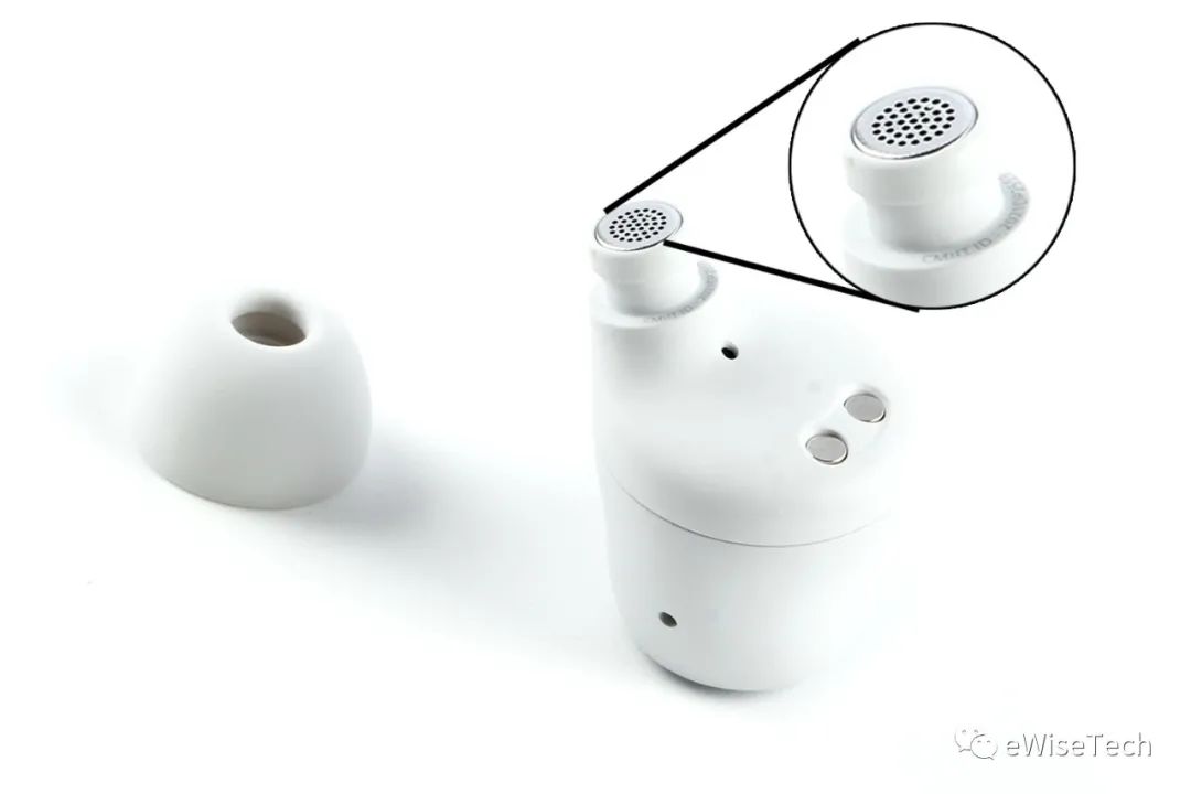
First take off the earplugs. There is a fine dust-proof net at the sound outlet.
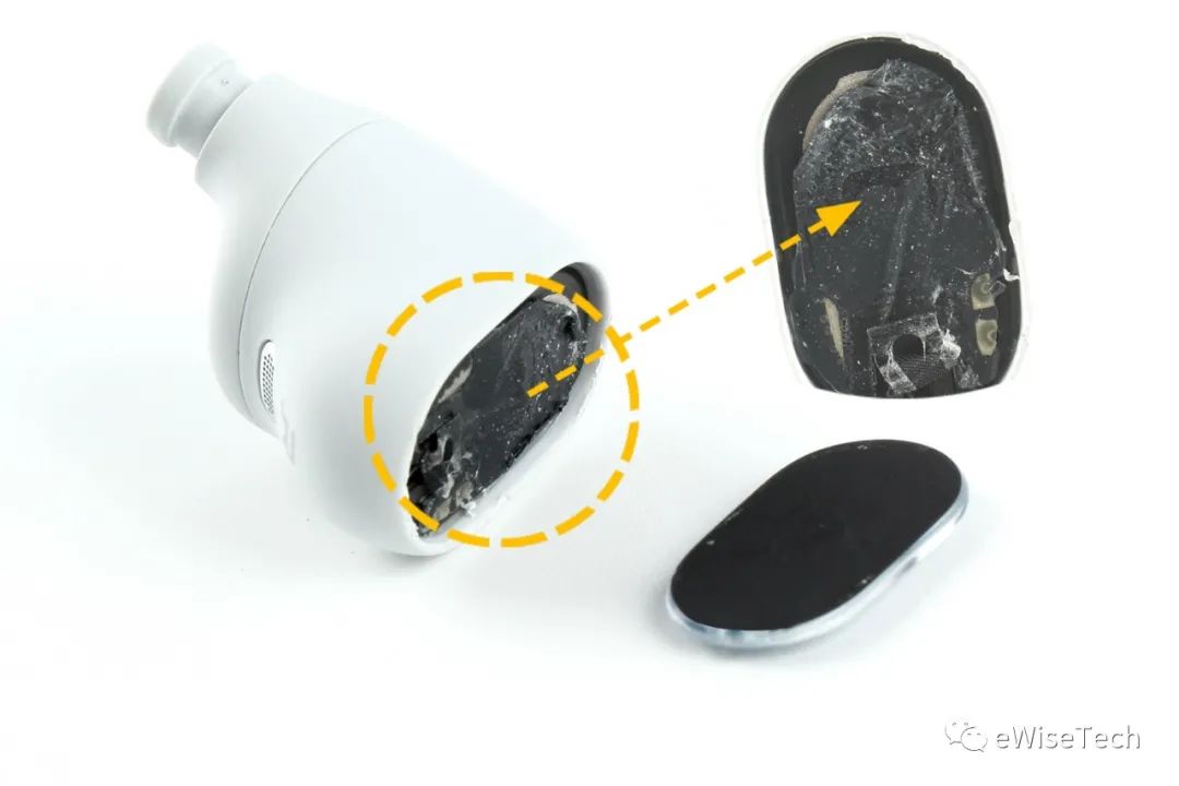
Remove the touch back panel and pry open the cavity along the mold line. The touch sensor covers the antenna module.
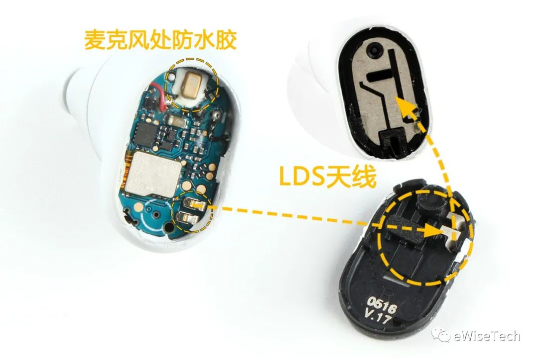
The antenna is an LDS antenna, which can be seen after removing the touch sensor. The antenna is connected through the spring clip on the motherboard. At the microphone position, you can see that it is coated with white silicone for waterproofing, and there is a dustproof net at the corresponding position of the antenna board.
Still pry open the middle frame along the mold line. The rear parts are connected by a soft board and fixed by translucent glue on the side of the BTB interface. Disconnect the BTB interface first and separate the middle frame and the front shell.
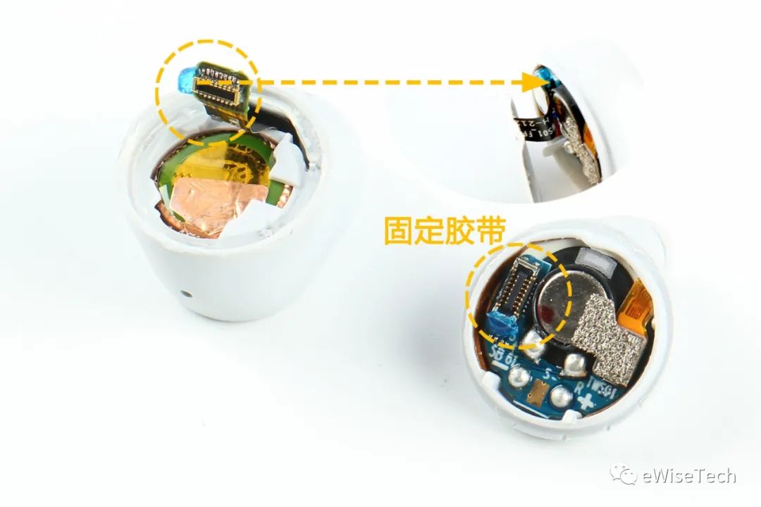
There is a plastic protective cover on the top of the battery. Pry off the protective cover and you will find copper foil around the battery.
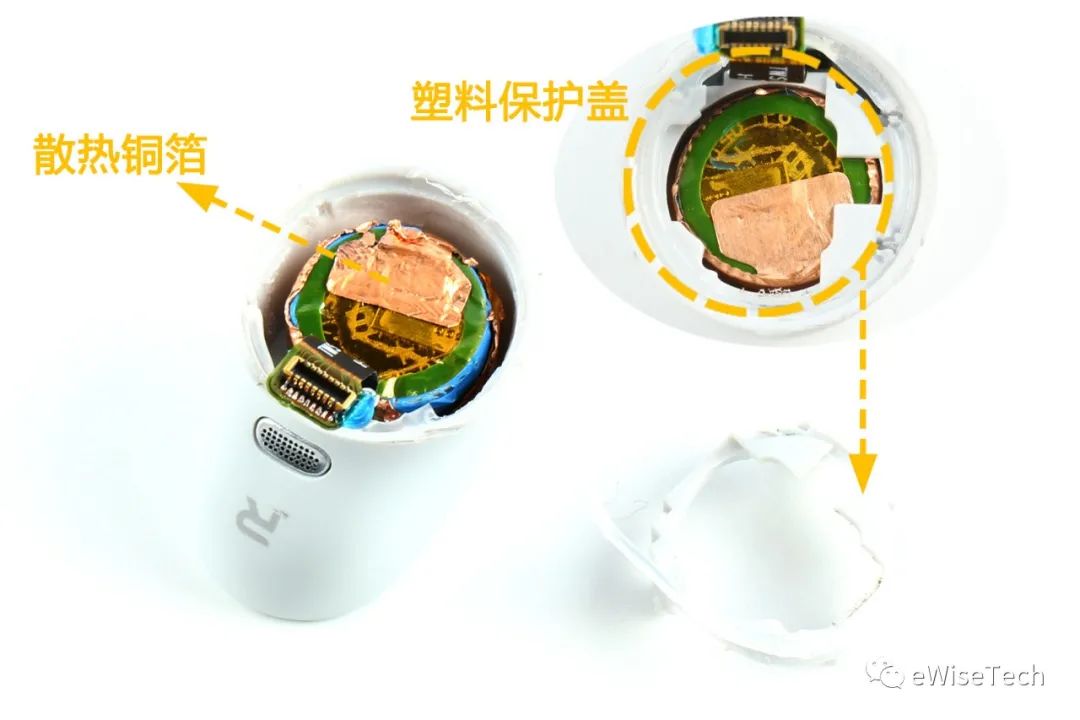
Disconnect the BTB connector on the motherboard and the positive and negative wires of the battery, and remove the motherboard. There is also a lot of waterproof silicone on the microphone of the motherboard.
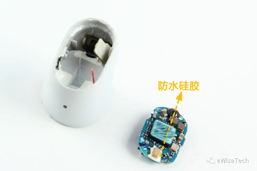
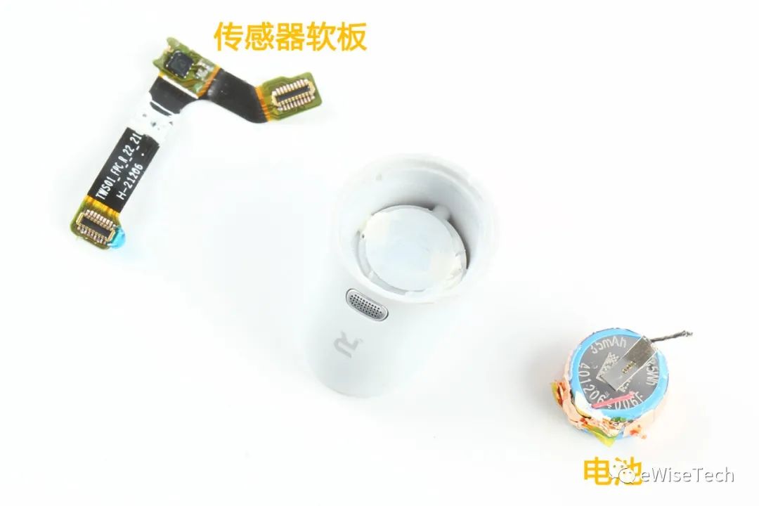
Inside the middle frame there is also a sensor board that connects the mainboard and the adapter board, as well as a battery, which can be taken out directly.
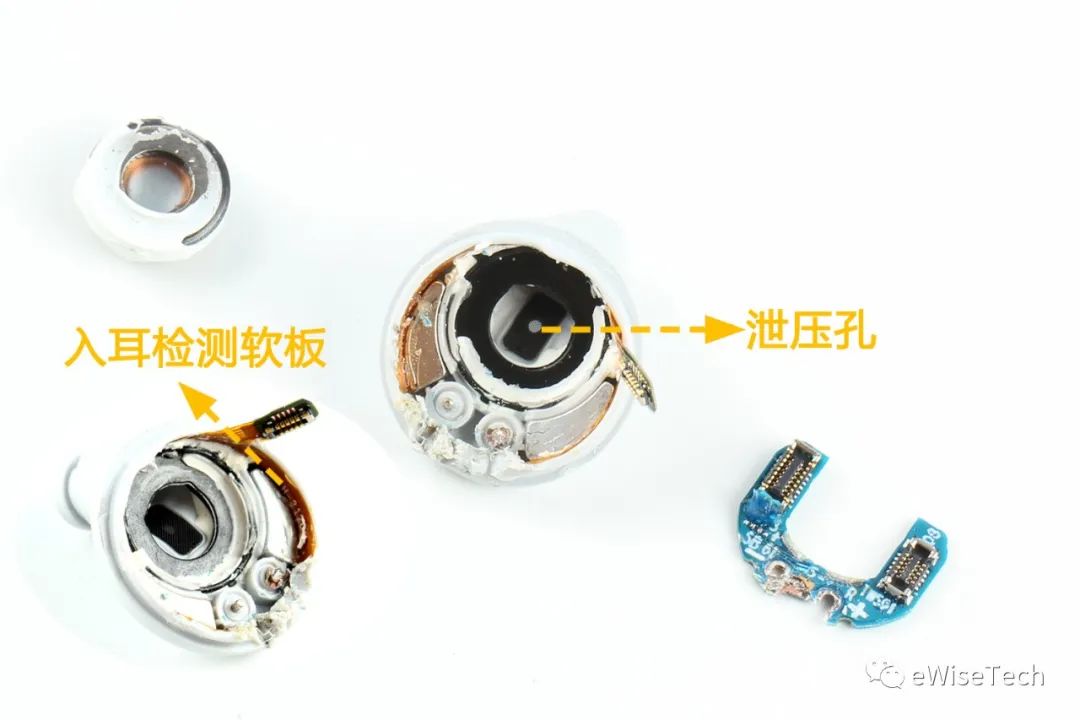
Remove the speaker and adapter board inside the front shell. The speaker is welded to the adapter board. Conductive foam is attached to the connector on the board. The charging contacts are also welded directly to the adapter board. There is a circle of yellow capacitive in-ear detection soft board inside the front shell, with magnets on both sides for adsorbing the charging box, and a dustproof net attached to the pressure relief hole below.
Charging box disassembly
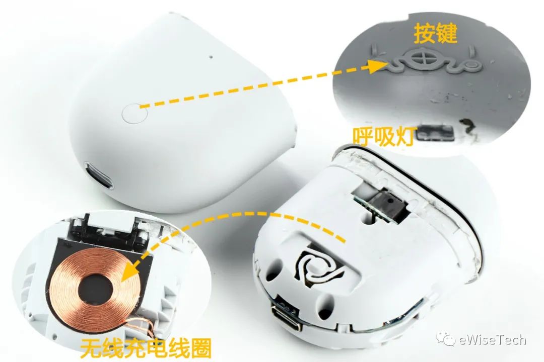
After prying off the outer shell of the charging box, you can see the buttons at the bottom and the transparent plastic sheet at the position of the breathing light inside the shell. The back of the charging box is the wireless charging coil.
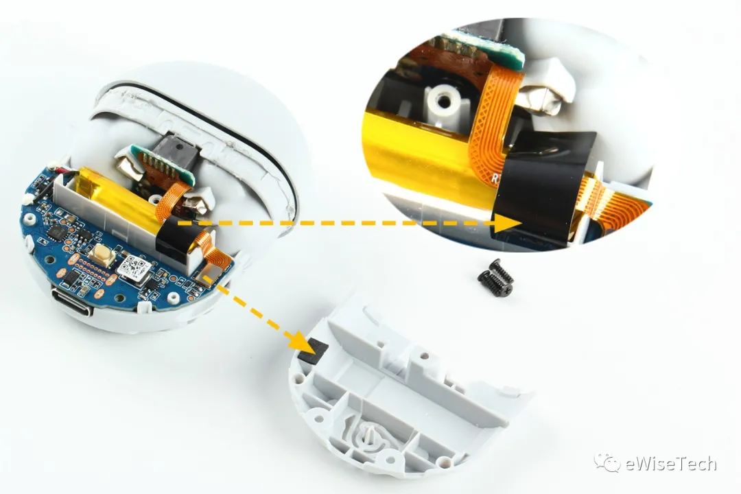
Unscrew the screws and remove the plastic shell covering the motherboard. There is a plastic sticker on the PFC board for fixing the PFC board, and there is black foam on the plastic shell corresponding to the BTB interface.
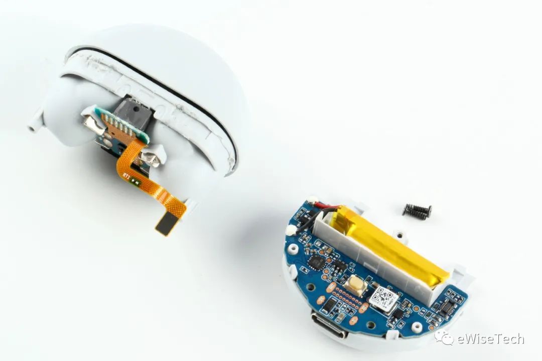
Unscrew the two screws on both sides to separate the inner support and the motherboard.
There are two screws on the inner support to fix the top shell of the charging box. Unscrew the screws and remove the top shell of the charging box. The FPC part of the charging board has a reinforcement plate fixed on the inner support and fixed by hot melt.
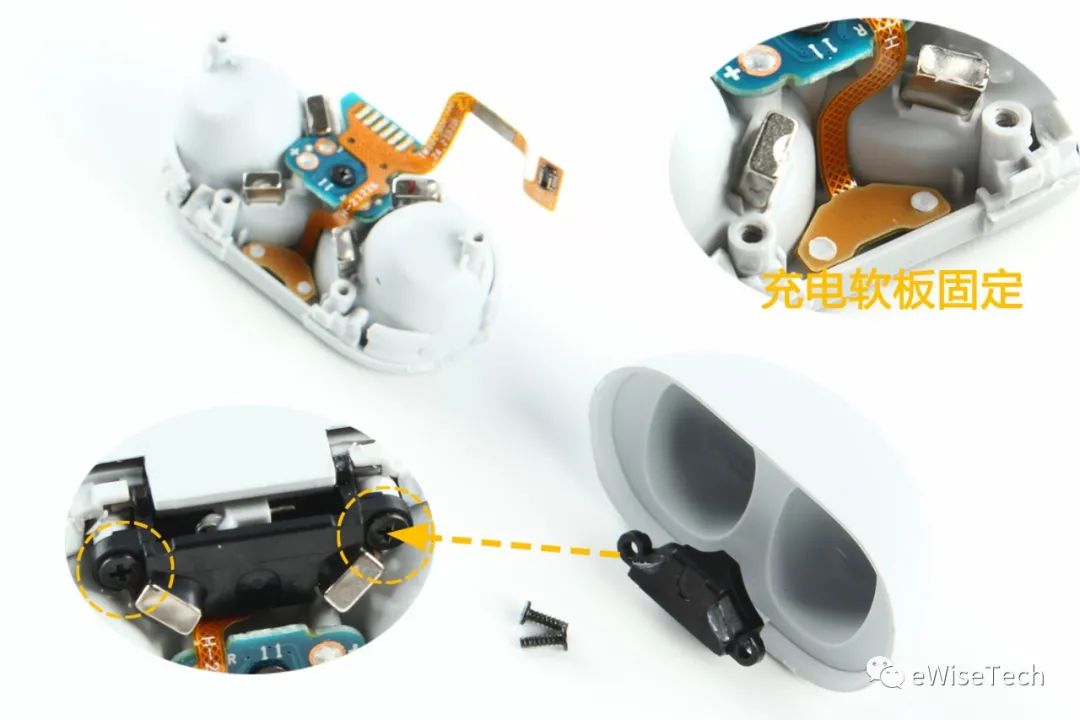
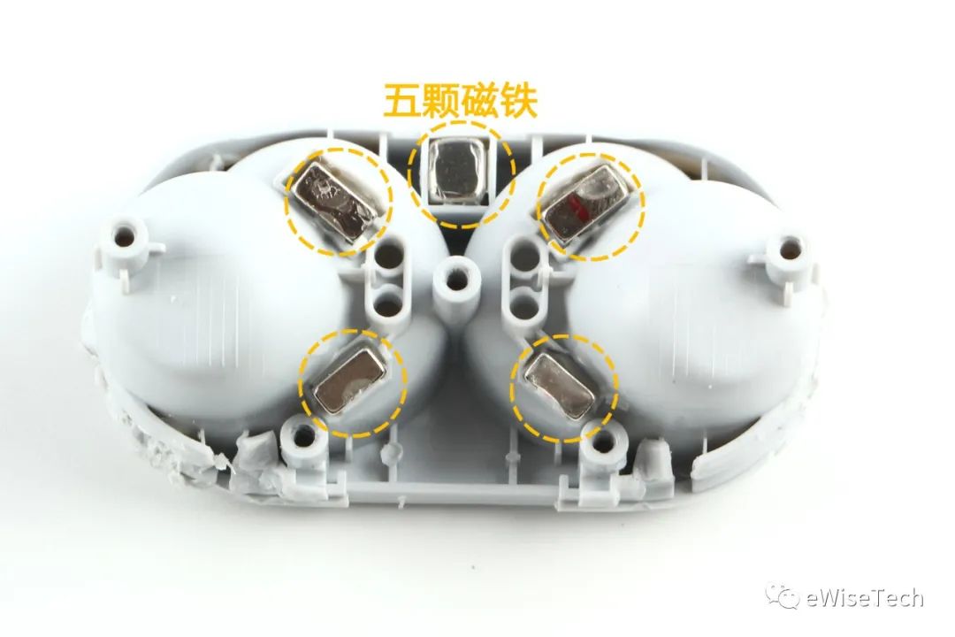
There are five magnets on the inner support, which are used to absorb the earphones and the top shell of the charging box.
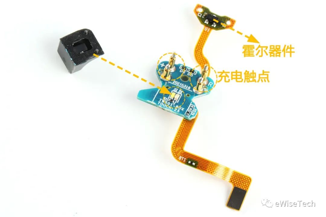
There is a plastic lampshade on the charging board, and two SMD LEDs are under the lampshade. The charging contacts are four spring pins. There is a Hall sensor on the upper FPC board. It is used to sense the opening and closing of the charging box.
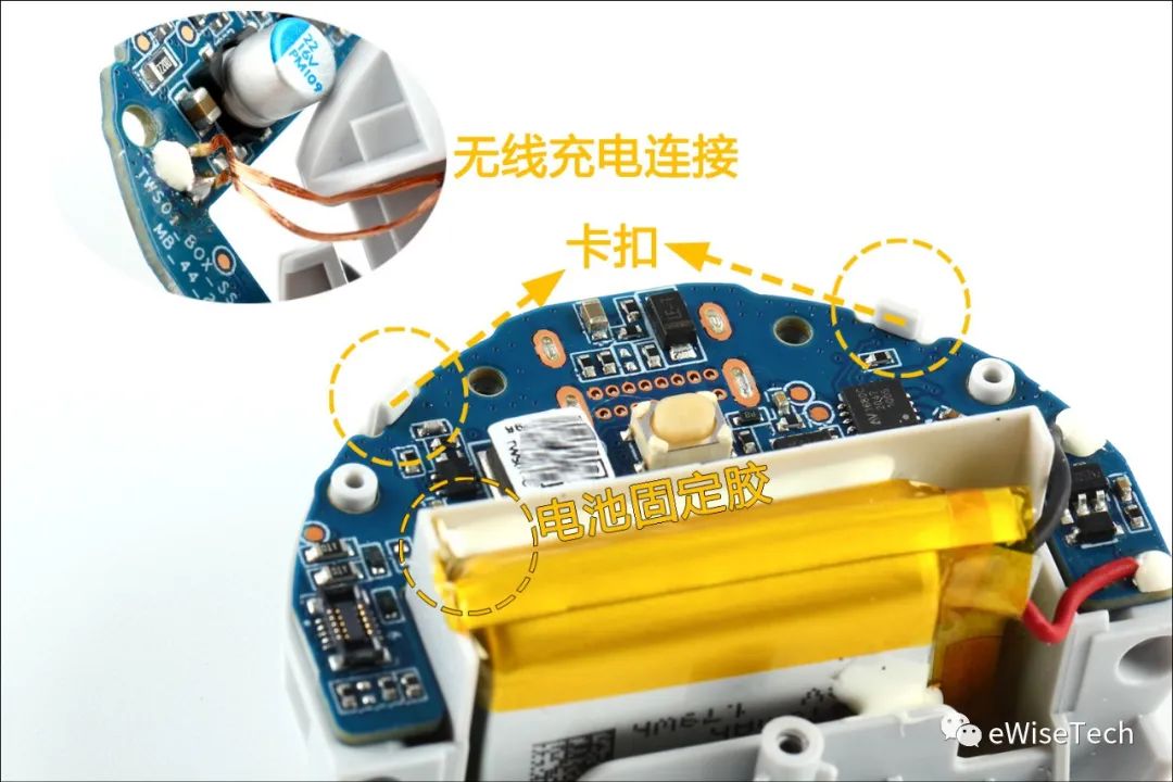
The motherboard is fixed with a clip. However, the battery and wireless charging coil are directly soldered to the motherboard with wires, so disconnect the wires and remove the motherboard. The battery is fixed to the shell with glue.
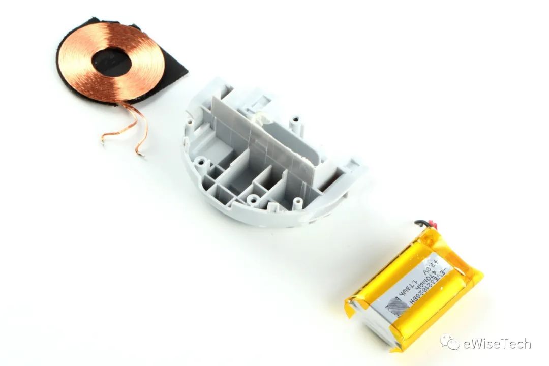
Finally, you can remove the battery and wireless charging coil on the outer shell.
E-Analysis
Headphone motherboard IC (below):
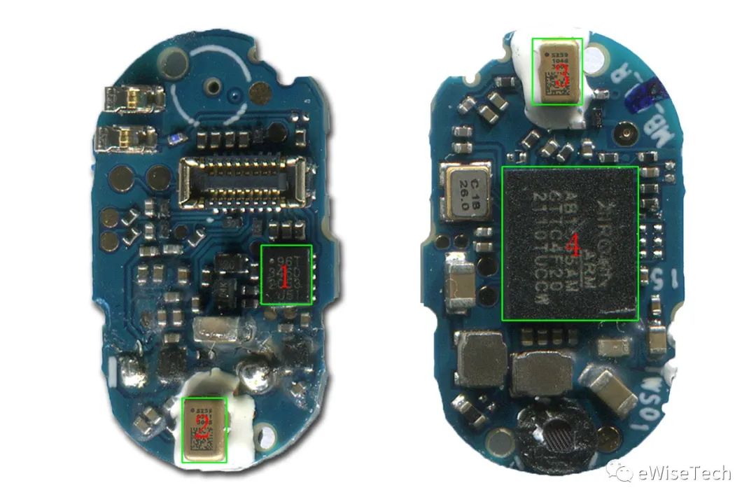
1: ABOV-capacitive touch MCU
2: Knowles - Microphone 3: Knowles - Microphone 4: AIROHA - Bluetooth 5.2 SoC Charging box motherboard IC (below):
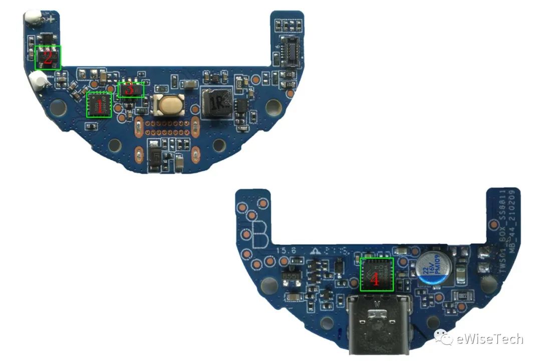
1: Nuvolta-wireless charging receiver chip
2: XYSemi - Lithium battery protection IC 3: ETA - Overvoltage protection IC 4: Sinhmicro - 8051 core MCU with integrated charge and discharge management
Summary Information
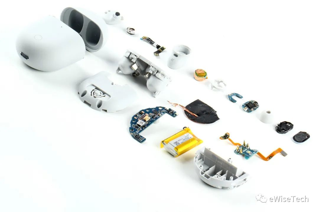
The entire headset has relatively many parts. The headset uses a front shell and a middle frame. The back cover has a three-section structure design. The Bluetooth antenna is an LDS antenna design. The entire headset uses two PCB boards, two FPC boards and a touch sensor board. Due to the problem of waterproofness, a lot of white silicone is used not only in the microphone, but also inside the front shell and the middle frame. After disassembling the inside of the charging box, it is relatively rare to use a separate plastic lampshade on the LED light. And the charging box has added a wireless charging function, and the wireless charging chip uses a chip from Volta Semiconductor. (Editor: Judy)
Previous article:Let's take a look at this domestic material - GigaDevice GD30WS8805 review
Next article:Huawei EMUI 12 is launched quietly, it is not Hongmeng system!
Recommended ReadingLatest update time:2024-11-17 02:39


- Huawei's Strategic Department Director Gai Gang: The cumulative installed base of open source Euler operating system exceeds 10 million sets
- Analysis of the application of several common contact parts in high-voltage connectors of new energy vehicles
- Wiring harness durability test and contact voltage drop test method
- Sn-doped CuO nanostructure-based ethanol gas sensor for real-time drunk driving detection in vehicles
- Design considerations for automotive battery wiring harness
- Do you know all the various motors commonly used in automotive electronics?
- What are the functions of the Internet of Vehicles? What are the uses and benefits of the Internet of Vehicles?
- Power Inverter - A critical safety system for electric vehicles
- Analysis of the information security mechanism of AUTOSAR, the automotive embedded software framework
 Professor at Beihang University, dedicated to promoting microcontrollers and embedded systems for over 20 years.
- Innolux's intelligent steer-by-wire solution makes cars smarter and safer
- 8051 MCU - Parity Check
- How to efficiently balance the sensitivity of tactile sensing interfaces
- What should I do if the servo motor shakes? What causes the servo motor to shake quickly?
- 【Brushless Motor】Analysis of three-phase BLDC motor and sharing of two popular development boards
- Midea Industrial Technology's subsidiaries Clou Electronics and Hekang New Energy jointly appeared at the Munich Battery Energy Storage Exhibition and Solar Energy Exhibition
- Guoxin Sichen | Application of ferroelectric memory PB85RS2MC in power battery management, with a capacity of 2M
- Analysis of common faults of frequency converter
- In a head-on competition with Qualcomm, what kind of cockpit products has Intel come up with?
- Dalian Rongke's all-vanadium liquid flow battery energy storage equipment industrialization project has entered the sprint stage before production
- Allegro MicroSystems Introduces Advanced Magnetic and Inductive Position Sensing Solutions at Electronica 2024
- Car key in the left hand, liveness detection radar in the right hand, UWB is imperative for cars!
- After a decade of rapid development, domestic CIS has entered the market
- Aegis Dagger Battery + Thor EM-i Super Hybrid, Geely New Energy has thrown out two "king bombs"
- A brief discussion on functional safety - fault, error, and failure
- In the smart car 2.0 cycle, these core industry chains are facing major opportunities!
- Rambus Launches Industry's First HBM 4 Controller IP: What Are the Technical Details Behind It?
- The United States and Japan are developing new batteries. CATL faces challenges? How should China's new energy battery industry respond?
- Murata launches high-precision 6-axis inertial sensor for automobiles
- Ford patents pre-charge alarm to help save costs and respond to emergencies
- Please advise, where can I modify the USB device instance path generated by STM32?
- Msp430f149 microcontroller controls stepper motor C language program
- dsp reports an error after importing a new project!
- [NXP Rapid IoT Review] Adding Bluetooth Capabilities with NXP Rapid IoT
- On the saturation problem of operational amplifier circuit
- sdram_datasheet.pdf
- CC2640R2F hardware RF from design to production
- The book on switching power supplies states that because the capacitor is charged in each cycle, the current decline slope continues to increase. How do you understand this?
- [TI recommended course] #In-depth study of light load high efficiency and low noise power supply reference design for wearable devices and the Internet of Things (TIDA-01566)#
- Channel explanation in wireless communication

 EDB (Evan s Debugger) is a QT4 based binary mode debugger with the goal of having usability on par w
 pic hex file disassembly to asm file
 ES2860 Maintenance Information


 京公网安备 11010802033920号