1 Introduction
At present, there are not many design schemes for embedded Ethernet, most of which are based on single-chip microcomputers, but the disadvantages are slow speed and high cost. DSP, as a special embedded microprocessor system, has an embedded coprocessor and parallel data channels for fast data processing. Introducing DSP technology in embedded network devices can make embedded Ethernet faster, cheaper and easier to expand functions. This paper introduces the interface circuit and implementation method of the embedded system based on TMS320LF2407 and the LAN91C111 adaptive 10Mb/s/100Mb/s embedded Ethernet control chip.

2 LAN91C111
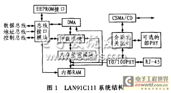
LAN91C111 is the third generation Fast Ethernet controller launched by SMSC for embedded application systems. The LAN91C111 chip integrates MAC (media layer) and PHY (physical layer) that follow the SMSC/CD protocol and complies with the IEEE802.3/802.U-100Base-Tx/10Base-T specification. Its system structure is shown in Figure 1. The main functions of this Ethernet controller are as follows:
Adaptively select the transmission rate, support 10Mb/s/100Mb/s;
Fully support full-duplex switched Ethernet;
Support burst data transmission;
8k bytes of internal memory used as FIFO buffer for receiving and sending;
Enhanced energy management capabilities;
Support bus 8-bit, 16-bit, 32-bit CPU access;
Send and receive in advance.
The LAN91C111 Ethernet controller complies with the 802.3 Ethernet transmission protocol promulgated by IEEE. Its 8-32-bit data bus interface unit is connected to the external CPU through the control bus, address bus and data bus. External data can be exchanged with the LAN91C111 in 8-bit, 16-bit or 32-bit mode. The circuit also integrates an EEPROM interface, which is input into the chip through the EEPROM interface during booting to achieve automatic initialization. The bus arbiter is used to monitor the data exchange of the Ethernet bus. Once a blockage occurs, the arbiter communicates with the external CPU through the bus interface unit on the one hand, and controls the memory control unit (MMU) on the other hand to achieve bus data coordination. The memory control unit can control the storage of the 8kB dynamic SRAM to achieve data communication with the DMA controller. The DMA controller and the bus controller together control the data exchange between the DMA and the Ethernet protocol processor (EPH). Data exchange between Ethernet protocol processors (EPH). The data from the Ethernet protocol processor finally reaches the Ethernet bus directly through the 10Mb/s/100Mb/s physical layer (PHY).

3 Hardware circuit composition
Considering the cost performance, the DSP controller is selected as the main CPU. TMS320LF2407 is a cost-effective DSP released by TI, suitable for the field of industrial control. This series has a powerful instruction system, strong flexibility, high-speed mathematical processing function and a brand-new internal structure, and can be widely used in communication, computer, business, industry, military and other fields. TMS320LF2407 is the most powerful one in the 240X series controller. It adopts low-power CMOS technology, has an execution rate of 30MI/s, and also integrates a rich peripheral components (EVM, A/D module, CAN, SCI, SPI and JTAG) on the chip. TMS320LF2407 has a high operating frequency (40MHz) and a large storage space (up to 32k words of FLASH program memory, can be expanded to an external 64k word memory, 64k word I/O addressing space), which is very suitable for processing complex TCP/IP protocols.
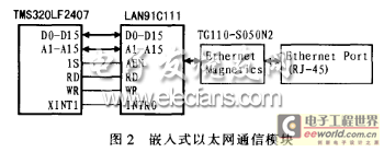
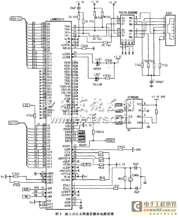
Since LAN91C111 is designed for embedded systems, its peripheral circuit is relatively simple. The embedded Ethernet structure composed of it, a 16-bit DSP (TMS320LF2407) without DMA transmission performance and a TG110-S050N2 electromagnetic coupling transformer is shown in Figure 2. In the figure, the address bus A1-A15 is connected. A0 is not used by LAN91C111 and is suspended; the data bus D0-D15 is connected and used for 16-bit data transmission. The LAN91C111 end D16-D32 is suspended; the chip select signal AEN of LAN91C111 is provided by the external I/O interface selection signal IS of the DSP. The read level RD and write level WR of the two components are connected respectively. The interrupt output signal INTRO of LAN91C111 is sent to the external interrupt pin XINT1 of DSP to trigger the interrupt. The circuit principle of the embedded Ethernet communication module is shown in Figure 3.
Embedded Ethernet can not only be used in industrial sites to realize the automatic Internet access function of field nodes, but also can be used for the Ethernet interface of information appliances to realize remote control, which has a good development prospect. This article introduces the interface circuit and software and hardware implementation method of the embedded system based on TMS320LF2407 DSP and LAN91C111 adaptive 10Mb/s/100Mb/s embedded Ethernet control.
TX INT: set to 1e when the TX completion FIFO is not empty;
TX EMPTY INT: set to when TX FIFO is empty;
AUTO RELEASE: If set to 1, after the packet is successfully sent, the packet number is not written to the TX completion FIFO, and the storage space it uses is automatically released.

(7) When using the "generate an interrupt for each packet sent" scheme, AUTO RELEASE=0, and the process of this scheme is as described above. When using the "generate an interrupt for each packet sent in a sequence" scheme, TX EMPTY INT and TX INT are allowed, AUTORELEASE=1, and a TX EMPTY INT interrupt is generated after the last packet in the FIFO is sent. If a serious transmission error occurs, a TX INT interrupt is generated, and the packet number of the failed packet is saved in the FIFO Ports register, so that the DSP can know that the transmission process has stopped. This scheme can reduce the burden on the DSP, and the storage space is released more quickly. When AUTO RELEASE=1, the DSP cannot obtain the packet number of the successfully transmitted packet.
4.2.3 Data packet receiving process
(1) The DSP sets the RXEN bit in the receive control register to allow packet reception.
(2) When a packet with the correct address is received, storage space is requested from the MMU and a packet number is assigned. The internal DMA logic generates continuous addresses and writes the received words to the memory. If the address exceeds the boundary, the packet is discarded and the storage space is released. When the end of the packet is detected, the Status Word is written to the front of the received packet and the byte count is written to the second word. If the CRC check is correct, the packet number is written to the RX FIFO. Since the RX FIFO is not empty, an RCV INT interrupt will be generated. If the RCR check is incorrect, the storage space is released and no interrupt is generated.
(3) After receiving the interrupt, the DSP starts to execute the interrupt processing program. First, it reads the Interrupt Status register. If a receive interrupt is generated (RCV INT bit is 1), the packet number of the received packet can be obtained from the FIFO ports register, and the received packet can be transferred to the DSP's internal memory or external memory from the data register. When the processing is completed, the DSP sends the REMOVE AND RELEASE FROM TOP OF RX command to the processor (that is, setting the register MMUCOM to 0x0060) to release the used storage space and packet number.
5 Conclusion
The system can correctly access Fast Ethernet and has multiple functions such as 100/10Mbit/s, full-duplex/half-duplex self-adaptation, and complies with IEEE802.3/802.3μ-100Base-TX/1Obase-T specifications. Its embedded Ethernet interface supports RJ45 and Ethernet connection, and can access the Internet through Ethernet, thereby realizing the monitoring of embedded devices from the Internet.
Previous article:A Design of Reconfigurable DSP System Based on NiosⅡ
Next article:Design of a new weft insertion control system for air jet loom based on FPGA+DSP
- Huawei's Strategic Department Director Gai Gang: The cumulative installed base of open source Euler operating system exceeds 10 million sets
- Analysis of the application of several common contact parts in high-voltage connectors of new energy vehicles
- Wiring harness durability test and contact voltage drop test method
- Sn-doped CuO nanostructure-based ethanol gas sensor for real-time drunk driving detection in vehicles
- Design considerations for automotive battery wiring harness
- Do you know all the various motors commonly used in automotive electronics?
- What are the functions of the Internet of Vehicles? What are the uses and benefits of the Internet of Vehicles?
- Power Inverter - A critical safety system for electric vehicles
- Analysis of the information security mechanism of AUTOSAR, the automotive embedded software framework
 Professor at Beihang University, dedicated to promoting microcontrollers and embedded systems for over 20 years.
- Innolux's intelligent steer-by-wire solution makes cars smarter and safer
- 8051 MCU - Parity Check
- How to efficiently balance the sensitivity of tactile sensing interfaces
- What should I do if the servo motor shakes? What causes the servo motor to shake quickly?
- 【Brushless Motor】Analysis of three-phase BLDC motor and sharing of two popular development boards
- Midea Industrial Technology's subsidiaries Clou Electronics and Hekang New Energy jointly appeared at the Munich Battery Energy Storage Exhibition and Solar Energy Exhibition
- Guoxin Sichen | Application of ferroelectric memory PB85RS2MC in power battery management, with a capacity of 2M
- Analysis of common faults of frequency converter
- In a head-on competition with Qualcomm, what kind of cockpit products has Intel come up with?
- Dalian Rongke's all-vanadium liquid flow battery energy storage equipment industrialization project has entered the sprint stage before production
- Allegro MicroSystems Introduces Advanced Magnetic and Inductive Position Sensing Solutions at Electronica 2024
- Car key in the left hand, liveness detection radar in the right hand, UWB is imperative for cars!
- After a decade of rapid development, domestic CIS has entered the market
- Aegis Dagger Battery + Thor EM-i Super Hybrid, Geely New Energy has thrown out two "king bombs"
- A brief discussion on functional safety - fault, error, and failure
- In the smart car 2.0 cycle, these core industry chains are facing major opportunities!
- Rambus Launches Industry's First HBM 4 Controller IP: What Are the Technical Details Behind It?
- The United States and Japan are developing new batteries. CATL faces challenges? How should China's new energy battery industry respond?
- Murata launches high-precision 6-axis inertial sensor for automobiles
- Ford patents pre-charge alarm to help save costs and respond to emergencies
- The role of dual MOS in communication interface
- MSP430 non-simulated IIC bus control program
- IGBT Safe Operating Area (SOA)
- Share the predictions for the 2021 eSports Contest
- Smart Home Energy Management with Levarys and Qorvo Technologies
- RF Energy Harvesting Technology
- 【Perf-V Review】Lighting Experiment
- [Raspberry Pi 4B Review] + DLNA Server Setup
- ATtiny85 Mini Violin
- MicroPython Hands-on (12) - Hello World on the Control Board

 STM32Cube embedded software for STM32F7 series


 京公网安备 11010802033920号