| Abstract: This article introduces the functional characteristics of a new type of microcontroller serial port expansion chip and the application of the interface with the microcontroller. Keywords: Single-chip microcomputer; Multi-serial port communication When designing a data acquisition circuit composed of multiple single-chip computers, multiple serial ports are generally used for data communication between each single-chip computer. In order to solve the problem of expanding multiple serial ports on a single-chip microcomputer, multiple AT89C2051 chips were mostly used to achieve multi-serial port communication. Each AT89C2051 is connected to the host computer through a parallel port, and then connected to the serial port of the lower computer through the serial port of AT89C2051. For this kind of circuit design, the microcontroller programming is more complicated, the debugging of the entire circuit is also more troublesome, and the reliability is not very high. A newly developed SP2328 serial port expansion chip solves the above problems very well. SP2328 is a dedicated serial port expansion chip of Chengdu Shipu Technology Company. It can expand one serial port (UART) of ordinary microcontrollers (such as AT89C2051, AT89C51, etc.) into three serial ports. It mainly solves the problem of too few UART serial ports in most 8-bit, 16-bit and 32-bit microcontrollers, and expands the scope of use of microcontrollers. At the same time, the SP2328 serial port expansion dedicated chip also solves many complex serial port configuration problems when using dual serial port microcontrollers, which can greatly shorten the development cycle and reduce development and production costs.
Figure 1 DIP and SOIC package (left) Figure 2 SSOP package (right) Functional features of SP2328 K=2400*f(osc)/8.0(bps) Among them, f(osc)<=16.0MHZ
Figure 3 Interface circuit between SP2328 and microcontroller
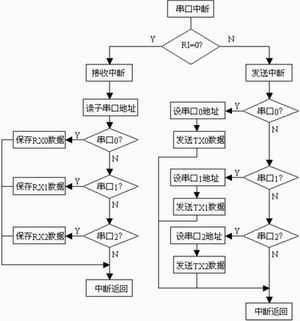
Example of the interface between SP2328 and the microcontroller. Issues that need attention Conclusion References |
Previous article:Implementation scheme of LIN protocol based on ordinary microcontroller
Next article:SP2328 serial port expansion special chip and its interface circuit with microcontroller
 Professor at Beihang University, dedicated to promoting microcontrollers and embedded systems for over 20 years.
- Innolux's intelligent steer-by-wire solution makes cars smarter and safer
- 8051 MCU - Parity Check
- How to efficiently balance the sensitivity of tactile sensing interfaces
- What should I do if the servo motor shakes? What causes the servo motor to shake quickly?
- 【Brushless Motor】Analysis of three-phase BLDC motor and sharing of two popular development boards
- Midea Industrial Technology's subsidiaries Clou Electronics and Hekang New Energy jointly appeared at the Munich Battery Energy Storage Exhibition and Solar Energy Exhibition
- Guoxin Sichen | Application of ferroelectric memory PB85RS2MC in power battery management, with a capacity of 2M
- Analysis of common faults of frequency converter
- In a head-on competition with Qualcomm, what kind of cockpit products has Intel come up with?
- Dalian Rongke's all-vanadium liquid flow battery energy storage equipment industrialization project has entered the sprint stage before production
- Allegro MicroSystems Introduces Advanced Magnetic and Inductive Position Sensing Solutions at Electronica 2024
- Car key in the left hand, liveness detection radar in the right hand, UWB is imperative for cars!
- After a decade of rapid development, domestic CIS has entered the market
- Aegis Dagger Battery + Thor EM-i Super Hybrid, Geely New Energy has thrown out two "king bombs"
- A brief discussion on functional safety - fault, error, and failure
- In the smart car 2.0 cycle, these core industry chains are facing major opportunities!
- The United States and Japan are developing new batteries. CATL faces challenges? How should China's new energy battery industry respond?
- Murata launches high-precision 6-axis inertial sensor for automobiles
- Ford patents pre-charge alarm to help save costs and respond to emergencies
- New real-time microcontroller system from Texas Instruments enables smarter processing in automotive and industrial applications
- The use of SRAM in HPM6750 and the problems encountered
- Oscilloscope automobile turbocharger solenoid valve waveform and analysis
- Transformer voltage calculation
- Failure to send data in broadcast mode
- EEWORLD University - IGBT module technology, drive and application
- Mbed online compiler to be retired soon
- New China Mobile Onenet NB Development Board
- PicoPlanet – Development board with capacitive touch
- Looking for the distributor of Sonix SN8P2501DSG chip
- 【Qinheng CH582】2, Compilation environment + the first LED program


 Design paper of dot matrix electronic display screen
 *** *** *** *** *** *** ***** ** Two wire/I2C Bus READ/WRITE Sample Routines of Microchip s ** 2
 HMC441LH5


 京公网安备 11010802033920号