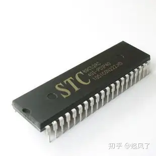
[1] Introduction to microcontroller pins


1. Power pin
●VSS: Ground.
●VCC: external 5V power supply.
2. External crystal oscillator pin
●XTAL1: When the microcontroller uses the internal oscillation circuit, connect one end of the external crystal and the trimmer capacitor. When the microcontroller uses an external clock signal, this pin is connected to ground.
●XTAL2: When the microcontroller uses the internal oscillation circuit, connect one end of the external crystal and the trimming capacitor. When the microcontroller uses an external clock signal, it is used to input clock pulses.
3. Control pin
●RST/VPD: Reset signal input terminal, active at high level. A reset operation occurs when this pin remains high for two machine cycles. The secondary function of this pin is backup power.
●ALE/PROG: Address latch enable signal terminal. When the MCS-51 microcontroller is powered on, the ALE pin continuously outputs a positive pulse signal of the oscillator frequency fosc 1/6. This pin has the second function PROG, which serves as the programming pulse input terminal when writing a firmware program to a microcontroller with on-chip programmable ROM.
●EA/VPP: External program memory address enable input terminal. When the EA pin is connected to high level, the CPU first accesses the on-chip program memory and executes the instructions therein, and then accesses the external program memory. When the EA pin is connected to low level, the CPU only accesses the external program memory and executes the instructions therein, regardless of whether the microcontroller has on-chip program memory. The second function of this pin is as a programming power supply when programming an EPROM microcontroller.
●PSEN: Program storage enable output signal terminal. When accessing the off-chip program memory, this pin outputs a negative pulse as a strobe signal for reading the off-chip memory. The PSEN signal is asserted twice per machine cycle while the CPU is fetching instructions from external program memory.
4. Input/output pin
●P0 port: 8-bit open-drain bidirectional I/O port, capable of driving 8 LS TTL loads. When accessing external memory, the low byte and data are transferred in a time-shared manner.
●P1 port: 8-bit quasi-bidirectional I/O port with internal pull-up resistor, capable of driving 4 LS TTL loads.
●P2 port: 8-bit quasi-bidirectional I/O port with internal pull-up resistor, capable of driving 4 LS TTL loads. When accessing external memory, the upper 8-bit address is output.
●P3 port: 8-bit quasi-bidirectional I/O port with internal pull-up resistor, capable of driving 4 LS TTL loads. In addition, it also has a second function, see Table 2.5.
【2】Program structure of C51
The C51 program is also composed of various functions. The most important one is the main() function, which is also a function that must exist. As the entry point of the program, each execution of the program starts from the main() function. After each other function is called, it will return to the main() function. When all the codes in the main() function are executed, the entire program ends. . The whole process does not care about the order of functions.
A function generally consists of two parts: the function description part and the function body part.
The function description part includes function name, function type, function attributes, and function parameters. The function name is followed by a parentheses () in which the function parameters are listed. A function can also have no parameters.
Immediately following the function description part is the function body part. The entire content of the function body is enclosed in curly brackets {}, which also includes variable descriptions and execution code. The code in the function is executed in sequence when the function is running.
The format of a standard C51 function is as follows.
Function type function name (function parameter list)
{
Variable description part;
Execute the code part;
}
The following is a practical example of a C51 function. The function of this function is to complete an addition operation.
int fun plus(int A, int B)
{
int result;
result=A+B;
return(result);
}
For users, C51 functions can use standard library functions or custom functions.
The standard library functions have been defined in the C51 library file and explained in the relevant header files. Users only need to call them directly.
Custom functions are a type of functions that users define and call according to their own needs.
Below is a complete example of C51 program structure.
#include void main(void) //Main function part { sbit P1.0=P1^0; //P1 port bit definition sbit P1.1=P1^1; P1.0=1; //Assign initial value to the variable defined by bit P1.1=1; delay(); //Call the delay subroutine while(1) //P1.0 and P1.1 are assigned values alternately to achieve the effect of LED flashing alternately. { P1.0=0; P1.1=1; delay(); P1.0=1; P1.1=0; delay(); } } void delay (void) //Delay subroutine part { uint i; for(i=0;i<256;i++); } For users, they only need to connect the anodes of the two LEDs to high level, connect a resistor in series and then connect them to the P1^0 and P1^1 pins of the MCS-51 microcontroller respectively. Using the above code, the LEDs can flash alternately. Effect. This is a small, successful C51 program, as you can see, it clearly includes header files and program themes. The header file contains hardware information and provides usable function and variable descriptions for external modules. The P1^0 of sbit P1.0=P1^0 in the program code is defined in the header file reg52.h. The program functions include main() function and custom sub-function delay(). During the running of the main() function, the sub-function is called multiple times to implement the delay function, so that the LED flashes are not so fast that the human eye cannot distinguish it. The microcontroller circuit corresponding to this program is shown in Figure 4.1. Keil is used to develop the MCS-51 microcontroller C51 program, and projects are usually used for management. Projects are generally divided into two large blocks: C file blocks and header file blocks. Write different functions in different C files, rely on project management, and finally connect all files to obtain a HEX file or BIN file that can be burned. In all these C files, there is one and only one main() function, and the header file connects the various C files to each other. Figure 4.1 LED flashes alternately microcontroller circuit diagram
Previous article:The case of zero-based entry-level microcontroller (3) is a kind of external memory
Next article:Proteus entry-level microcontroller (4) routine analysis
- Popular Resources
- Popular amplifiers
- Naxin Micro and Xinxian jointly launched the NS800RT series of real-time control MCUs
- How to learn embedded systems based on ARM platform
- Summary of jffs2_scan_eraseblock issues
- Application of SPCOMM Control in Serial Communication of Delphi7.0
- Using TComm component to realize serial communication in Delphi environment
- Bar chart code for embedded development practices
- Embedded Development Learning (10)
- Embedded Development Learning (8)
- Embedded Development Learning (6)
 Professor at Beihang University, dedicated to promoting microcontrollers and embedded systems for over 20 years.
- Intel promotes AI with multi-dimensional efforts in technology, application, and ecology
- ChinaJoy Qualcomm Snapdragon Theme Pavilion takes you to experience the new changes in digital entertainment in the 5G era
- Infineon's latest generation IGBT technology platform enables precise control of speed and position
- Two test methods for LED lighting life
- Don't Let Lightning Induced Surges Scare You
- Application of brushless motor controller ML4425/4426
- Easy identification of LED power supply quality
- World's first integrated photovoltaic solar system completed in Israel
- Sliding window mean filter for avr microcontroller AD conversion
- What does call mean in the detailed explanation of ABB robot programming instructions?
- Europe's three largest chip giants re-examine their supply chains
- Breaking through the intelligent competition, Changan Automobile opens the "God's perspective"
- The world's first fully digital chassis, looking forward to the debut of the U7 PHEV and EV versions
- Design of automotive LIN communication simulator based on Renesas MCU
- When will solid-state batteries become popular?
- Adding solid-state batteries, CATL wants to continue to be the "King of Ning"
- The agency predicts that my country's public electric vehicle charging piles will reach 3.6 million this year, accounting for nearly 70% of the world
- U.S. senators urge NHTSA to issue new vehicle safety rules
- Giants step up investment, accelerating the application of solid-state batteries
- Guangzhou Auto Show: End-to-end competition accelerates, autonomous driving fully impacts luxury...
- Design of screen self-checking program based on FPGA
- Application of Siemens PLC and inverter in centrifuge
- Live FAQ|Fujitsu FRAM non-encryption algorithm (spectrum) authenticity verification solution
- Based on STM32F303 dual motor FOC driver: sensorless schematic/BOM/code and other open source sharing
- (C- Wireless Charging Electric Car) 2018TI Cup Wireless Charging Car
- Do popular chargers also need double pulse testing? Download the information to learn more and get gifts!
- Computer System Architecture Q&A
- Please recommend a stackup of single-layer FPC with electromagnetic shielding film
- Radio Frequency Identification Technology and Its Application Development Trend
- MSP430F5529 ADC Reference

 MAX9508ATE+


 京公网安备 11010802033920号