When configuring the external line interrupt of the PC13 pin, the multiplexing function is used when configuring its external clock:
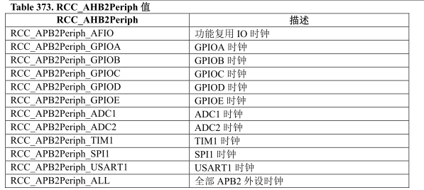
RCC_APB2PeriphClockCmd(RCC_APB2Periph_GPIOC|RCC_APB2Periph_AFIO,ENABLE);
The reason is that the first function pin of PC13 is GPIO, and the second function pin is TAMER-RTC1, which does not have the EXTI function. If you want to use it to generate an external line interrupt, you must configure the AFIO multiplexing function and map the EXTI function to the PC13 pin.
PC13 pin function diagram
Another example:
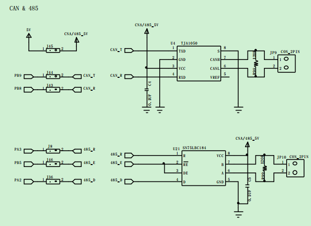
The CAN bus uses PB8 and PB9, but these two pins do not have CAN functions and need to be remapped:
RCC_APB2PeriphClockCmd(RCC_APB2Periph_AFIO | RCC_APB2Periph_GPIOB, ENABLE);
PB8, PB9 pin function diagram
CAN&485 TR pin diagram
Some configurations do not require multiplexing functions, for example, UASRT1 pins PA9 and PA10, whose second function pins are USART functions, so when using the UASRT function, the clock cannot be configured in AFIO.
When configuring the RCC external clock, you need to configure both the basic GPIO mode and the clock of its second function USART.
The second pin of PA9 is used, and one of the output modes is the multiplexed output mode, so it needs to be configured into the multiplexed output mode.
GPIO_InitStructure.GPIO_Mode = GPIO_Mode_AF_PP;
Since both USART and GPIOA are externally connected to RCC_APB2, the parameter is a combination of the two values.
/* config USART1 clock */
RCC_APB2PeriphClockCmd(RCC_APB2Periph_USART1 | RCC_APB2Periph_GPIOA, ENABLE);
Previous article:Aliases of R0~R15 registers in ARM registers
Next article:When does the STM32 AFIO clock need to be turned on?
Recommended ReadingLatest update time:2024-11-16 16:03


- Popular Resources
- Popular amplifiers
 Professor at Beihang University, dedicated to promoting microcontrollers and embedded systems for over 20 years.
- Innolux's intelligent steer-by-wire solution makes cars smarter and safer
- 8051 MCU - Parity Check
- How to efficiently balance the sensitivity of tactile sensing interfaces
- What should I do if the servo motor shakes? What causes the servo motor to shake quickly?
- 【Brushless Motor】Analysis of three-phase BLDC motor and sharing of two popular development boards
- Midea Industrial Technology's subsidiaries Clou Electronics and Hekang New Energy jointly appeared at the Munich Battery Energy Storage Exhibition and Solar Energy Exhibition
- Guoxin Sichen | Application of ferroelectric memory PB85RS2MC in power battery management, with a capacity of 2M
- Analysis of common faults of frequency converter
- In a head-on competition with Qualcomm, what kind of cockpit products has Intel come up with?
- Dalian Rongke's all-vanadium liquid flow battery energy storage equipment industrialization project has entered the sprint stage before production
- Allegro MicroSystems Introduces Advanced Magnetic and Inductive Position Sensing Solutions at Electronica 2024
- Car key in the left hand, liveness detection radar in the right hand, UWB is imperative for cars!
- After a decade of rapid development, domestic CIS has entered the market
- Aegis Dagger Battery + Thor EM-i Super Hybrid, Geely New Energy has thrown out two "king bombs"
- A brief discussion on functional safety - fault, error, and failure
- In the smart car 2.0 cycle, these core industry chains are facing major opportunities!
- The United States and Japan are developing new batteries. CATL faces challenges? How should China's new energy battery industry respond?
- Murata launches high-precision 6-axis inertial sensor for automobiles
- Ford patents pre-charge alarm to help save costs and respond to emergencies
- New real-time microcontroller system from Texas Instruments enables smarter processing in automotive and industrial applications


 usb_host_device_code
 Transplantation of real-time operating system RT-ThreadSmart on STM32MP1


 京公网安备 11010802033920号