Independent LED lights can realize running lights, digital tubes can display multiple digits, and dot matrix LEDs have to display some patterns.
When we want to display patterns, we often have to make some small graphics first. The data of these small graphics needs to be converted into our program. At this time, we need modeling software. Here is a simple modeling software that can be downloaded online. Let's learn how to use it. First, take a look at the operation interface, as shown in Figure 7-3.

Figure 7-3 Font extraction software interface
Click "New Shape" with the mouse, change the width and height to 8 respectively according to the dot matrix on our board, and then click OK, as shown in Figure 7-4.

Figure 7-4 Create a new graphic
Click the "Simulation Animation" menu on the left, then click the "Enlarge Grid" option and zoom in to the maximum. Then we can use the mouse to fill in the black dots in our 8*8 dot matrix and draw the graphics, as shown in Figure 7-5.

Figure 7-5 Drawing with font extraction software
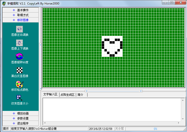
After careful design, we drew a heart-shaped figure and filled it up, and finally the desired effect appeared, as shown in Figure 7-6.

Figure 7-6 Heart-shaped graphic
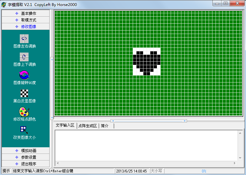
Since the modeling software sets black as 1 and white as 0, but our dot matrix corresponds to 1 when the LED is off and 0 when the LED is on, and what we need is a lit "heart", we need to select the "Black and white reverse image" option in the "Modify image" menu, and then click "Save image" in the "Basic operation" menu to save the image we designed, as shown in Figure 7-7.

Figure 7-7 Save the graph
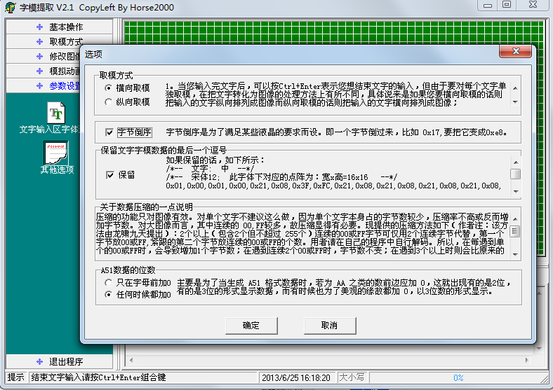
Saving the file is just for the convenience of reuse or modification. Of course, you can choose not to save it. After completing this step, click "Other Options" in the "Parameter Settings" menu, as shown in Figure 7-8.

Figure 7-8 Option settings
The options here should be set in conjunction with Figure 7-2. You can see that port P0 controls a row, so use "horizontal modulus". If it controls a column, select "vertical modulus". The "byte reverse order" option is selected because the left side of Figure 7-2 is low-order DB0 and the right side is high-order DB7, so it is byte reverse order. You can understand the other two options yourself. After clicking OK, select the "modulus mode" menu. After clicking "C51 format", 8 bytes of data are automatically generated in the "dot matrix generation area". These 8 bytes of data are the "modulus" taken out, as shown in Figure 7-9.

Figure 7-9 Modulo result
Please note that although we use software to take the modulus, we also need to know the principle. In this picture, a black grid represents a binary 1, and a white grid represents a binary 0. The first byte is 0xFF, which is actually the first row of this 8*8 graphic. All black is 0xFF; the second byte is 0x99, with the low bit on the left and the high bit on the right. Please note that black represents 1 and white represents 0, which constitutes the value 0x99. Similarly, you will know how the other data comes from.
Then we will use the program to send these data to the dot matrix in turn to see how the operation effect is.
#include
sbit ADDR0 = P1^0;
sbit ADDR1 = P1^1;
sbit ADDR2 = P1^2;
sbit ADDR3 = P1^3;
sbit ENLED = P1^4;
unsigned char code image[] = { //Character table of the image
0xFF, 0x99, 0x00, 0x00, 0x00, 0x81, 0xC3, 0xE7
};
void main(){
EA = 1; // Enable general interrupt
ENLED = 0; // Enable U4 and select LED matrix
ADDR3 = 0;
TMOD = 0x01; //Set T0 to mode 1
TH0 = 0xFC; //Assign the initial value 0xFC67 to T0, and the timing is 1ms
TL0 = 0x67;
ET0 = 1; // Enable T0 interrupt
TR0 = 1; //Start T0
while (1);
}
/* Timer 0 interrupt service function */
void InterruptTimer0() interrupt 1{
static unsigned char i = 0; //dynamic scan index
TH0 = 0xFC; //Reload initial value
TL0 = 0x67;
//The following code completes the dynamic scanning and refreshing of the LED dot matrix
P0 = 0xFF; //display blanking
switch (i) {
case 0: ADDR2=0; ADDR1=0; ADDR0=0; i++; P0=image[0]; break;
case 1: ADDR2=0; ADDR1=0; ADDR0=1; i++; P0=image[1]; break;
case 2: ADDR2=0; ADDR1=1; ADDR0=0; i++; P0=image[2]; break;
case 3: ADDR2=0; ADDR1=1; ADDR0=1; i++; P0=image[3]; break;
case 4: ADDR2=1; ADDR1=0; ADDR0=0; i++; P0=image[4]; break;
case 5: ADDR2=1; ADDR1=0; ADDR0=1; i++; P0=image[5]; break;
case 6: ADDR2=1; ADDR1=1; ADDR0=0; i++; P0=image[6]; break;
case 7: ADDR2=1; ADDR1=1; ADDR0=1; i=0; P0=image[7]; break;
default: break;
}
}
For 8*8 dot matrix, we can display some simple graphics, characters, etc. But most Chinese characters usually use 16*16 dots, and 8*8 dot matrix can only display some Chinese characters with simple strokes. You can try it yourself. The method of using a large screen to display Chinese characters is similar to that of a small screen. All you need to do is expand the number of rows and columns according to the same principle.
Previous article:Introduction of LED dot matrix
Next article:Vertical movement of LED dot matrix
 Professor at Beihang University, dedicated to promoting microcontrollers and embedded systems for over 20 years.
- Innolux's intelligent steer-by-wire solution makes cars smarter and safer
- 8051 MCU - Parity Check
- How to efficiently balance the sensitivity of tactile sensing interfaces
- What should I do if the servo motor shakes? What causes the servo motor to shake quickly?
- 【Brushless Motor】Analysis of three-phase BLDC motor and sharing of two popular development boards
- Midea Industrial Technology's subsidiaries Clou Electronics and Hekang New Energy jointly appeared at the Munich Battery Energy Storage Exhibition and Solar Energy Exhibition
- Guoxin Sichen | Application of ferroelectric memory PB85RS2MC in power battery management, with a capacity of 2M
- Analysis of common faults of frequency converter
- In a head-on competition with Qualcomm, what kind of cockpit products has Intel come up with?
- Dalian Rongke's all-vanadium liquid flow battery energy storage equipment industrialization project has entered the sprint stage before production
- Allegro MicroSystems Introduces Advanced Magnetic and Inductive Position Sensing Solutions at Electronica 2024
- Car key in the left hand, liveness detection radar in the right hand, UWB is imperative for cars!
- After a decade of rapid development, domestic CIS has entered the market
- Aegis Dagger Battery + Thor EM-i Super Hybrid, Geely New Energy has thrown out two "king bombs"
- A brief discussion on functional safety - fault, error, and failure
- In the smart car 2.0 cycle, these core industry chains are facing major opportunities!
- The United States and Japan are developing new batteries. CATL faces challenges? How should China's new energy battery industry respond?
- Murata launches high-precision 6-axis inertial sensor for automobiles
- Ford patents pre-charge alarm to help save costs and respond to emergencies
- New real-time microcontroller system from Texas Instruments enables smarter processing in automotive and industrial applications
- Precision control techniques and methods for PCB board milling
- EEWORLD大学堂----Modern Robotics: Mechanics, Planning, and Control
- Microcontroller Basics
- Which PCB teaching video is more reliable?
- STM32 pin short circuit to ground analysis
- DSP core + coprocessor
- [Zero-knowledge ESP8266 tutorial] Advanced 3 SSDP Simple Service Discovery Protocol
- DC 48V60V72V85V to 5V2A 12V2A switching power supply circuit
- SST25 series memory architecture issues
- Working conditions of three states of circuit

 Basic Program for writing a picture to Newhaven Display Graphic COG
 LCD DRIVER Details


 京公网安备 11010802033920号