1 Composition of constant current source system
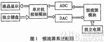
The PIC microcontroller is used as the core control device in this paper. The block diagram of the constant current source system is shown in Figure 1, which is mainly composed of a microcontroller circuit module, an ADC circuit module, a DAC circuit module, a constant current source control drive and a current sampling circuit module. The system realizes simple human-computer communication through an LCD display and an independent keyboard; the LCD display displays the current value and some corresponding functions, and the keypad is used to realize the manual control of the constant current source output. The PIC microcontroller uses a general-purpose microcontroller model PIC 24HJ64GP504, which has complete functions, high performance and low cost. It is the preferred core control chip for small control systems. The system uses a microcontroller to convert the current control value and the set value into the output of the DAC through conversion, and the output is controlled by the constant current source drive circuit. After the output current is collected and amplified, it is sent to the ADC and fed back to the microcontroller control system. The output of the constant current source current is adjusted by compensation calculation in the microcontroller, thereby achieving the purpose of improving the output accuracy and stability.
2 Main circuit design of constant current source system
2.1 Constant current source circuit design
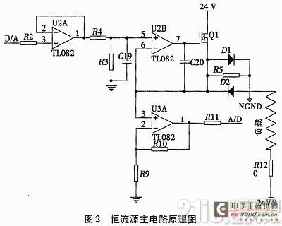
The principle structure diagram of the constant current source circuit is shown in Figure 2. The control of the constant current source current is mainly achieved by controlling the gate voltage of the power MOSFET tube. The single-chip microcomputer sends the digital value of the set or adjusted value to the DAC through the SPI bus to convert it into an analog signal, and then sends it to the constant current source control after the op amp follower and R4 and R3 voltage division, thereby realizing the regulation of the constant current source current. While controlling the constant current source current, the control system samples the current size back through the sampling resistor R5, and sends it to the ADC chip after amplification by the amplifier, thereby realizing the real-time monitoring of the output current by the single-chip microcomputer. When the monitored current is different from the set value, the output current will be adjusted through this closed-loop feedback link. When the load size is changed, the current output is basically not affected under this regulation. As shown in Figure 2, since the current and power of the constant current source are both large, if the same power supply is used as the main control circuit, it will affect the stability of the entire system. Therefore, an independent power supply is used. The power supply uses a 24 V power supply with a loop end, which makes the power supply of the control circuit and the constant current source independent of each other and does not affect each other.
2.2 PIC microcontroller and peripheral circuits
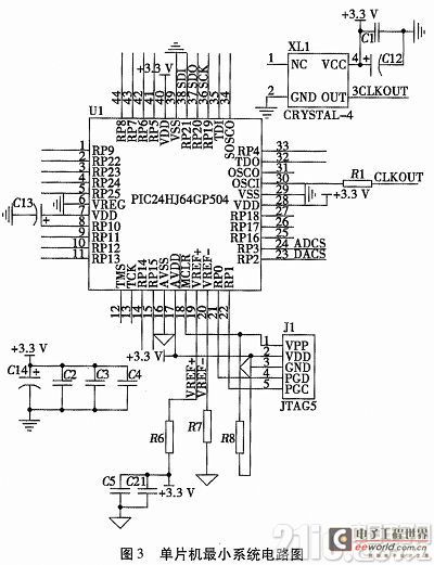
The PIC single-chip control system is the control core of the entire constant current source, which is mainly composed of a single-chip microcomputer, a crystal oscillator, a programming and debugging interface, and a filter capacitor. The minimum system circuit is shown in Figure 3. The MCU uses the PIC24HJ64GP504 single-chip microcomputer of PIC Company. This single-chip microcomputer is a low-power, high-performance 16-bit microcontroller with 64 k in-system programmable Flash memory, a crystal oscillator frequency of up to 40 MHz, 8 k bytes of RAM, 44 pins, and 5 16-bit timers/counters. At the same time, it has the advantages of low power consumption, small size, and mature technology.
2.3 ADC acquisition circuit design
The ADC acquisition input circuit is shown in Figure 4. In order to meet the sampling accuracy requirements, we choose the 12-bit ADC converter TLV2541 chip; this ADC is a high-performance, 12-bit, low-power, COMS serial ADC with single-channel input and output interface SPI bus. There are three control lines: chip select (CS), serial clock (SCLK) and serial data output line (SDO). These three lines are directly connected to the SPI peripheral port of the PIC microcontroller. The ADC reference uses REF3225 to provide a 2.5 V reference voltage, which has the characteristics of low drift and high precision. This series of reference chips is particularly suitable for data acquisition. When reading data, TLV2541 needs to ensure strict timing requirements and give enough conversion time.

2.4 DAC Control Circuit Design
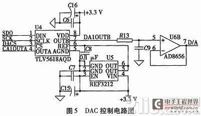
The DAC control output circuit is shown in Figure 5. The DAC uses TI's TLV5618. DACS, SDO, and SCK are connected to the SPI interface of the microcontroller. The microcontroller sends data to the DAC through the SPI protocol port and performs adjustment control. The output of the DAC is amplified by the op amp and sent to the constant current source circuit to adjust the current of the constant current source. TLV5618 is a 12-bit DAC. The current step size of each bit of the DAC can reach 1/4096A, which is far lower than the required accuracy. TLV5618 needs to be connected to an external reference voltage. REF3212 is selected in this article to provide a reference voltage of 1.25 V for the DAC. Its output voltage range is twice the reference voltage multiplied by the programming value.
3 System Software Design
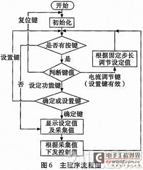
The software program flow chart of the control system is shown in Figure 6. After the system is powered on, the main program first completes the system initialization, including the setting of the working status of ADC, DAC, interrupt, timer/counter, etc., assigning initial values to system variables, displaying the last set value, etc. Then scan the keyboard, obtain the key value, and determine whether the function key is pressed. Once pressed, the corresponding function module will be executed; otherwise, the corresponding output digital quantity is calculated according to the set value, correction and other parameters, and sent to DAC to realize closed-loop feedback control.
4 Circuit Test Results and Analysis
Instruments used in the test: digital multimeter, 5 V and 24 V DC power supplies. In order to compare the error between the measured value and the true value, we selected 10 values between 0 A and 1 A for comparison, recorded the measured data and analyzed the error.
When the load is 10 Ω and the output current step is 10 mA, the comparison of the output current preset value, display value and test value is shown in Table 1.

The values shown in Table 1 are the data collected by ADC after filtering, and the measured values are the readings displayed by the multimeter. From the results in the table, it can be seen that the data after filtering is basically close to the current setting value, while there is a certain error between the multimeter measurement value and the program measurement value. This is mainly due to the error in the system measurement itself and the large ripple of the 24 V power supply used, which affects the multimeter reading. The program filters the ADC collected data to make its data more stable, but no matter which measurement value, its error with the setting value is within the required accuracy.

In order to better illustrate the performance of the constant current source system, the current values of different loads with the same set value are tested in this paper, and the test data are shown in Table 2. The test results show that although the constant current source has a small error when the load changes, it can basically ensure that its current value remains constant.
5 Conclusion
This paper uses PIC24HJ64GP504 microcontroller as the core control device, and uses DAC, ADC, operational amplifier and high-power MOSFET tube to form a negative feedback system to complete the measurement and control of the current of the entire constant current source system. This closed-loop feedback control method enables the constant current source current to be quickly and timely adjusted, enhancing the controllability and stability of the system; at the same time, it is also convenient to set the constant current source current value in the range of 0 A to 1 A through the keyboard. Even if the load changes greatly, the system can adjust the output current in time to make the current constant. In addition, the system has a simple circuit, low cost, high reliability, and has a broad market prospect and application value.
Previous article:System Design and Type Test of Single Chip Microcomputer Digital Timer
Next article:Design of DC motor servo system based on PWM module and CWG module
Recommended ReadingLatest update time:2024-11-16 14:49


- Popular Resources
- Popular amplifiers
 Professor at Beihang University, dedicated to promoting microcontrollers and embedded systems for over 20 years.
- Innolux's intelligent steer-by-wire solution makes cars smarter and safer
- 8051 MCU - Parity Check
- How to efficiently balance the sensitivity of tactile sensing interfaces
- What should I do if the servo motor shakes? What causes the servo motor to shake quickly?
- 【Brushless Motor】Analysis of three-phase BLDC motor and sharing of two popular development boards
- Midea Industrial Technology's subsidiaries Clou Electronics and Hekang New Energy jointly appeared at the Munich Battery Energy Storage Exhibition and Solar Energy Exhibition
- Guoxin Sichen | Application of ferroelectric memory PB85RS2MC in power battery management, with a capacity of 2M
- Analysis of common faults of frequency converter
- In a head-on competition with Qualcomm, what kind of cockpit products has Intel come up with?
- Dalian Rongke's all-vanadium liquid flow battery energy storage equipment industrialization project has entered the sprint stage before production
- Allegro MicroSystems Introduces Advanced Magnetic and Inductive Position Sensing Solutions at Electronica 2024
- Car key in the left hand, liveness detection radar in the right hand, UWB is imperative for cars!
- After a decade of rapid development, domestic CIS has entered the market
- Aegis Dagger Battery + Thor EM-i Super Hybrid, Geely New Energy has thrown out two "king bombs"
- A brief discussion on functional safety - fault, error, and failure
- In the smart car 2.0 cycle, these core industry chains are facing major opportunities!
- The United States and Japan are developing new batteries. CATL faces challenges? How should China's new energy battery industry respond?
- Murata launches high-precision 6-axis inertial sensor for automobiles
- Ford patents pre-charge alarm to help save costs and respond to emergencies
- New real-time microcontroller system from Texas Instruments enables smarter processing in automotive and industrial applications
- The difference between a two-pipe wired controller and a four-pipe thermostat
- Build a laser tripwire alarm using the MSP430 LaunchPad
- Switching power supply testing "Five rules"
- Source Insight Open Issues
- STM Arduion cannot download firmware?
- An article explains the function and principle of Via hole
- DSP IIR digital filter implementation program source code
- NXP Rapid IoT Review] +③ NXP Rapid IoT online compilation and operation of various demos
- Pressure measurement
- What is the use of this circuit? The input of the previous stage is the level of the comparator output

 ESP32-S3 source code
 【Follow me Season 2 Episode 2】Arduion UR4 homework submission code
 MCU C language programming and Proteus simulation technology (Xu Aijun)


 京公网安备 11010802033920号