2. What is "IO port"
3. Performance indicators of IO ports
Two states of IO port

As shown in the figure above (there is a selector switch that does not exist in the actual circuit, it is given for easy understanding) the output is either 5V or ground 0V
The ideal input IO port of the input model in the figure above
IO port output performance indicators
1/AVR's IO port current sinking and sourcing capabilities are both up to 30mA
2/51 source current capability <100uA, sink current capability 10mA
Current sourcing capability:
The maximum current that can flow from the IO port

Sink current capability:
The maximum current that can flow into the IO port
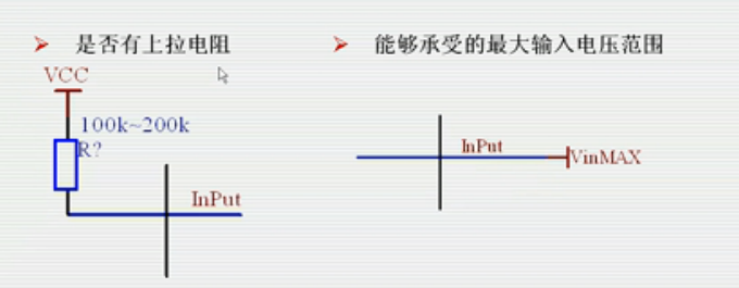
The following figure is similar to the IO port input

IO port input performance indicators
1. The pull-up resistor of AVR IO port can be configured in the input state, and the value is in the order of 100K
2. Maximum input voltage range: -0.5V~VCC+0.5V


Except for ATmega16, other AVR chips are similar to m16.
1. IO spoken IO register mapping (x represents A~D)\
Direction Register: DDRx
Data Register: PORTx
Input register: Pinx
2. Mapping of C language variables and registers
The io.h file maps all registers to variables with the same name. Reading and writing these variables is equivalent to reading and writing registers.
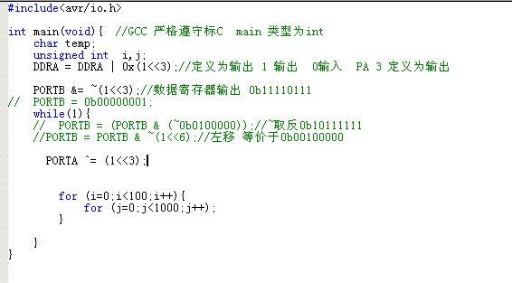
3. Output status IO register setting
When a certain DDRx position is set to 1, the corresponding IO port is set to output
A certain position of PORTx is 1 or 0, which corresponds to the level of the corresponding bit of the IO port


Here are some mapping relationships

First: C language is compiled into target code through AVR Studio/WinAVR, etc., and then downloaded to the hardware microcontroller through the download line programmer (now generally not used by individuals), JATG port
The second one is about the mapping of registers to registers through variables with the same name. Most microcontrollers are 8-bit timers, of course, there are also 16-bit counters, and then mapped to the data in the register 0 1. Although the RAM stores 0 or 1, it is equivalent to a form of internal high and low levels for storage. Finally, it is converted to +5v 0v or LVTTL +3.3V 0V through the IO port UART
Third, other variables are actually the data in the RAM, that is, the storage units in the RAM. Of course, this RAM cannot directly contact the outside world. [page]
Fourth, functions represent some operations and interactive relationships between various functions, which are manifested in the internal microcontroller as the interactive relationship between various registers and RAM, and finally converted into the relationship between hardware modules.
- C language running light verification
loop statement,
By shifting the IO register, you can achieve the effect of running lights.
loop statement
Flow lamp verification of various operators
Assignment =
AND&OR|Negation~
Logical AND && Logical OR ||
while(expression) //If the expression is not 0, it is true
{
}


How to set a breakpoint
toggle breakpoint F9
The breakpoint is when running at full speed and stops when it reaches the breakpoint position as shown below

Run

To remove a breakpoint, place the cursor at the breakpoint and click the little hand or F9 key again. The breakpoint will be removed.
Press full speed again and the result is as shown below: All lights are on

The reason is that the running loop speed is too fast and a delay should be added. The AVR CPU main frequency can run at 16MHZ for 1 to 2 microseconds. 1 million cycles per second, but the human eye cannot distinguish the delay.
for (assign the initial value only once; condition (true to enter the content); execute this statement after executing the content){}; judge the second and third statements back and forth
The for loop does not have curly braces, which means only the second and third judgments are executed.

Bitwise Operations
- Set a position to 1, 0, or invert
- Set 1,
Note: In 32-bit operating systems, it is the complement sign bit.
If the homemade simulator has a disadvantage and the filtering is not done well, the signal may fly away.
(Quote from Baidu: Program runaway
Program runaway means that after the system is disturbed by some kind of interference, the value of the program counter PC deviates from the given unique change history, causing the program to deviate from the normal running path. The factors and consequences of program runaway are often unpredictable. In many cases, after the program runaway, the system will enter an infinite loop and cause a crash.
)

Any number XORed with 1 will be inverted.
PORTB = PORTB ^ 0b11111111; // Use XOR to achieve flashing lights
IO port is set to output state
- buzzer
1. Active buzzer
When the power supply voltage is added, a beeping sound will be emitted, and the current consumption is about 20mA
Traditional buzzer driving circuit
Transistor drive (as shown below)

AVR buzzer driver circuit
IO port direct drive (as shown in the figure)

Write a program to verify (buzzer)


You can see that PORTA changes and
Okay, let’s summarize.
Step 1: Set IO as output
DDRB = 0XFF;
DDRB |= 0b00100000 //The fifth bit outputs high level
Step 2: Output data for corresponding bits
Output 1: PORTB |= 0b00100000; //The fifth bit outputs high level
Output 0: PORTB &= ~0b00100000; //The fifth bit outputs low level
Output 1: PORTB |= (1<<5); //The fifth bit outputs high level
Output 0: PORTB &= ~ (1<<5); //The fifth bit outputs low level
Corresponding bit inversion: PORTB^ = (1<<5); //The fifth bit outputs high level
Previous article:AVR MCU Learning (II) Hardware Circuit Design Tutorial
Next article:AVR MCU Learning (VI) Interrupts and Timers
Recommended ReadingLatest update time:2024-11-16 13:40


- Popular Resources
- Popular amplifiers
-
 Principles and Applications of Single Chip Microcomputers 3rd Edition (Zhang Yigang)
 -
 Metronom Real-Time Operating System RTOS for AVR microcontrollers
 -
 Learn C language for AVR microcontrollers easily (with video tutorial) (Yan Yu, Li Jia, Qin Wenhai)
 -
 ATmega16 MCU C language programming classic example (Chen Zhongping)
 Professor at Beihang University, dedicated to promoting microcontrollers and embedded systems for over 20 years.
- Innolux's intelligent steer-by-wire solution makes cars smarter and safer
- 8051 MCU - Parity Check
- How to efficiently balance the sensitivity of tactile sensing interfaces
- What should I do if the servo motor shakes? What causes the servo motor to shake quickly?
- 【Brushless Motor】Analysis of three-phase BLDC motor and sharing of two popular development boards
- Midea Industrial Technology's subsidiaries Clou Electronics and Hekang New Energy jointly appeared at the Munich Battery Energy Storage Exhibition and Solar Energy Exhibition
- Guoxin Sichen | Application of ferroelectric memory PB85RS2MC in power battery management, with a capacity of 2M
- Analysis of common faults of frequency converter
- In a head-on competition with Qualcomm, what kind of cockpit products has Intel come up with?
- Dalian Rongke's all-vanadium liquid flow battery energy storage equipment industrialization project has entered the sprint stage before production
- Allegro MicroSystems Introduces Advanced Magnetic and Inductive Position Sensing Solutions at Electronica 2024
- Car key in the left hand, liveness detection radar in the right hand, UWB is imperative for cars!
- After a decade of rapid development, domestic CIS has entered the market
- Aegis Dagger Battery + Thor EM-i Super Hybrid, Geely New Energy has thrown out two "king bombs"
- A brief discussion on functional safety - fault, error, and failure
- In the smart car 2.0 cycle, these core industry chains are facing major opportunities!
- The United States and Japan are developing new batteries. CATL faces challenges? How should China's new energy battery industry respond?
- Murata launches high-precision 6-axis inertial sensor for automobiles
- Ford patents pre-charge alarm to help save costs and respond to emergencies
- New real-time microcontroller system from Texas Instruments enables smarter processing in automotive and industrial applications
- Use MicroPython development board to read and display custom Chinese character library
- Test LWIP UDP (STM32H750/STM32H743) receiving 5913 and above, it will enter HardFault in about 5 seconds...
- EEWORLD University Hall----Robotics Technology and Applications
- Today's live broadcast: Nexperia's efficient ESD solutions for connected car applications
- GPCE4064B cannot be programmed
- “a data verification error occurred, file load failed” feasible solution
- Zhouyi Compass Simulation Experiment 2——Environment and Routine Analysis
- Collection! 19 methods and techniques for converting 5V to 3.3V
- Embedded C code optimization
- ESP32-S2-Saola-1 Review—by dcexpert

 Principles and Applications of Single Chip Microcomputers 3rd Edition (Zhang Yigang)


 京公网安备 11010802033920号