0 Introduction
In today's industrial and agricultural production, there are more and more occasions where temperature and humidity collection is required, and accurate and convenient temperature measurement has become crucial. Traditional wired temperature measurement methods have problems such as complex wiring, easy aging of lines, difficulty in troubleshooting line faults, and re-layout of equipment. Especially when the wired network is not smooth or it is inconvenient to set up lines due to limitations of on-site environmental factors, it brings great trouble to the data collection of temperature and humidity. In order to monitor real-time temperature and humidity data, it is necessary to use wireless transmission to collect, send, and receive data, and process the wirelessly collected data through the host computer to control and monitor the operation of the equipment and reduce unnecessary line equipment expenses.
1 System Block Diagram
The multi-channel wireless temperature and humidity detection system designed in this paper combines the single-chip detection control system with the radio frequency communication system. The system consists of two parts: the host and the slave. The slave is responsible for detecting temperature and humidity, and sends the collected data to the host through the radio frequency system. The host receives the signal sent by the slave and communicates with the PC through the serial port to record the data. At the same time, the upper and lower limits of the alarm data can be set through the PC. The system composition block diagram is shown in Figure 1.
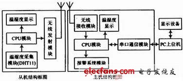
Figure 1 System composition block diagram
2 System Hardware Circuit
The system's temperature and humidity data are collected using a digital temperature and humidity sensor DHT11. The 51 series enhanced single-chip microcomputer STC12C5A08S2 is used as the core and the wireless radio frequency nRF2401 constitutes the transceiver circuit. The slave uses LCD1602 for display, and the host uses LCD12864 for display. The entire display system can be connected to a PC host computer.
2.1 Temperature and humidity acquisition circuit design
DHT11 is a temperature and humidity composite sensor with calibrated digital signal output. The sensor uses dedicated digital module acquisition technology and temperature and humidity sensing technology, with extremely high reliability and excellent long-term stability. Figure 2 shows its temperature acquisition circuit. The DHT11 sensor includes a resistive humidity sensing element and an NTC temperature measuring element, which can be connected to a high-performance 8-bit microcontroller. The calibration coefficients are stored in the OTP memory in the form of a program, and these calibration coefficients can be called in the sensor during the signal detection process. The single-wire serial interface makes system integration simple and fast, and the signal transmission distance can reach more than 20m. When the length of the connection line is shorter than 20m, a 5kΩ pull-up resistor should be used. When it is greater than 20m, a suitable pull-up resistor should be used according to the situation.
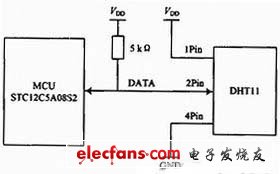
Figure 2 Temperature acquisition circuit
2.2 Wireless transmission and receiving circuit design
nRF24L01 is a wireless communication chip produced by NORDIC. It adopts FSK modulation and integrates NORDIC's own Enhanced Short Burst protocol. It can realize point-to-point or 1-to-6 wireless communication. The wireless communication speed can reach 2 Mb/s. The circuit schematic diagram of NORDIC wireless transmission and receiving chip nRF24L01 is shown in Figure 3.
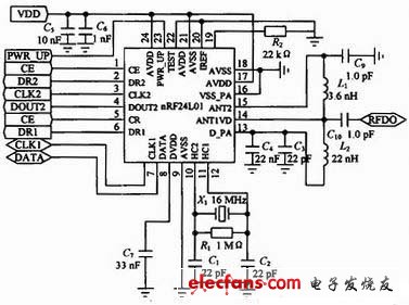
Figure 3 Schematic diagram of wireless transmission and reception
nRF24L01 is a single-chip RF transceiver chip that operates in the 2.4~2.5 GHz ISM band. The chip has built-in frequency synthesizer, power amplifier, crystal oscillator and modulator and other functional modules. The output power and communication channel can be configured through the program. The energy consumption of the nRF24L01 chip is very low. When transmitting at a power of -5 dBm, the operating current is only 10.5 mA, and when receiving, the operating current is only 18 mA. It has a variety of low-power operating modes, energy-saving and environmentally friendly, and easy to design. [page]
The functions of the pins of the nRF24L01 wireless transceiver module are listed in Table 1. Figure 4 shows the circuit diagram when the nRF24L01 is connected to the microcontroller.

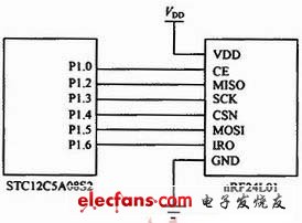
Figure 4: Circuit diagram of wireless module and CPU connection
The power supply required by this wireless transmitting and receiving module is 1.9~3.6 V. In this system, a 3.3 V DC power supply is used to directly power the wireless transmitting and receiving module. The 5 V power supply can be converted by the ASM1117-3.3 chip to obtain a stable DC power supply. The power conversion circuit is shown in Figure 5.
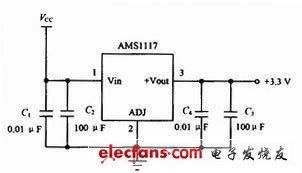
Figure 5 Wireless module power conversion circuit
2.3 Serial Communication Module
After the host microcontroller receives the data from nRF24L01, it can realize the download and upgrade of the microcontroller program through the MAX232 level conversion. At the same time, it can realize the communication between the microcontroller and the PC (host computer), so that the display data information can be transmitted to the PC through this circuit and displayed on the PC. The serial communication circuit is shown in Figure 6.
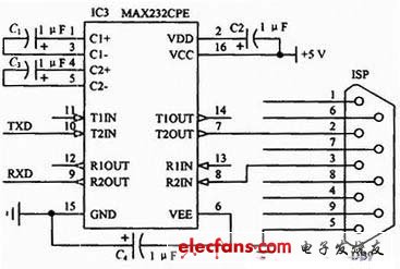
Figure 6 Serial communication circuit between MAX232CPE and PC
3 Software Design
3.1 Lower computer software
This system is programmed using C language. The complete structure of the system program should be determined according to the requirements of the design task. Modular programming methods should be used as much as possible to divide the tasks into relatively independent functional modules, and the functions, time sequence and relationships of each module should be clarified. The system software design can be divided into several parts. The first is the writing of the underlying driver programs of each module, followed by system online debugging, and finally the writing of the system program for the host computer.
The main program is the core of control and management. After the system is powered on, it is initialized first. After the system starts to operate normally, it then performs operations such as temperature and humidity monitoring and processing.
3.2 Host computer software design
The functions that the system host computer can complete include displaying the serial port number and prompting whether the serial port has been successfully opened; at the same time, the host computer can display the temperature synchronously with the lower computer, and can display the temperature in real-time curves; the host computer can set the lower limit temperature and humidity and the upper limit temperature and humidity, and can also alarm when it is higher than the upper limit temperature and humidity or lower than the lower limit temperature and humidity. After connecting the control circuit serial interface of the host microcontroller with the computer serial port through level conversion, select the correct communication protocol, set the baud rate, and then communication can be carried out. Figure 7 shows the operation interface of the host computer.
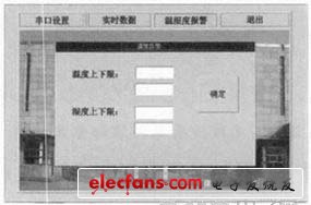
Figure 7 Host computer operation interface
The host computer software can be written on a PC using VC6.0, mainly to operate the MSComm control and the CserialPort class.
First is the serial port setting. This system uses the initialization function InitPort (this, nport, nbtl, 'N', 8, 1, m_dwCommEvents, 512) in the CSERIALPORT class. nport is the serial port number, and nbtl is the baud rate. The nport and nbtl in the initialization function can be obtained by using the serial port number and baud rate combo boxes in the serial port setting dialog box.
The second is to set the upper and lower limits of temperature and humidity. You can use the Start Monitoring function in the CSERIALPORT class, the WriteToPort function to send a string, and the StopMonitoring function to close the serial port process to set the upper and lower limits of temperature. The information is sent to the serial port through these functions. After the microcontroller receives the data from RS232, it compares it with its own temperature and then performs corresponding processing.
The third is curve display. Dynamic curve display can use the SetRange (200, 400) and SetPos (temp) functions in the CHistogram class. SetRange sets the upper and lower limits, SetPos displays the corresponding data points on the graph, and temp is the processing result of the temperature and humidity data transmitted from the single-chip microcomputer. The specific moving curve can be realized by the functions in the CHistogram class.
4 Conclusion
After testing, it is found that in most cases, the data transmission distance of the wireless transmitter and receiver module is about 200 m without an antenna. The transmission power of the transmitter head and the receiving sensitivity of the receiver head may affect the transmission distance. If an antenna is added, the transmission distance will be greatly increased. In addition, during the debugging process, the oscillation resistor must be matched, otherwise the receiving distance will be shortened or even unable to receive.
The digital signal of this system is sampled by the single-chip microcomputer. The real-time monitoring system composed of the digital temperature and humidity sensor based on DHT11 has many advantages such as high accuracy, strong anti-interference ability, simple circuit, etc. Then, the data can be sent to the PC for data storage, post-processing and display by using the communication between the single-chip microcomputer and the PC. This system has powerful data processing functions, intuitive display, friendly interface, and high cost performance. It can be widely used in many fields such as industrial control, instruments, meters, agricultural breeding and smart home.
Previous article:Design and implementation of temperature controller based on single chip microcomputer and fuzzy control
Next article:Design of intelligent control system for LED street lamps
Recommended ReadingLatest update time:2024-11-16 16:24


- Popular Resources
- Popular amplifiers
-
 MCU Principles and Interface Technology C51 Programming (Edited by Zhang Yigang)
 -
 51 Single Chip Microcomputer C Language Programming Classic Examples (2nd Edition) (Hou Yubao)
 -
 Build the Internet of Things with Arduino
 -
 Microcontroller Principles and Applications Tutorial (2nd Edition) (Zhang Yuanliang)
 Professor at Beihang University, dedicated to promoting microcontrollers and embedded systems for over 20 years.
- Innolux's intelligent steer-by-wire solution makes cars smarter and safer
- 8051 MCU - Parity Check
- How to efficiently balance the sensitivity of tactile sensing interfaces
- What should I do if the servo motor shakes? What causes the servo motor to shake quickly?
- 【Brushless Motor】Analysis of three-phase BLDC motor and sharing of two popular development boards
- Midea Industrial Technology's subsidiaries Clou Electronics and Hekang New Energy jointly appeared at the Munich Battery Energy Storage Exhibition and Solar Energy Exhibition
- Guoxin Sichen | Application of ferroelectric memory PB85RS2MC in power battery management, with a capacity of 2M
- Analysis of common faults of frequency converter
- In a head-on competition with Qualcomm, what kind of cockpit products has Intel come up with?
- Dalian Rongke's all-vanadium liquid flow battery energy storage equipment industrialization project has entered the sprint stage before production
- Allegro MicroSystems Introduces Advanced Magnetic and Inductive Position Sensing Solutions at Electronica 2024
- Car key in the left hand, liveness detection radar in the right hand, UWB is imperative for cars!
- After a decade of rapid development, domestic CIS has entered the market
- Aegis Dagger Battery + Thor EM-i Super Hybrid, Geely New Energy has thrown out two "king bombs"
- A brief discussion on functional safety - fault, error, and failure
- In the smart car 2.0 cycle, these core industry chains are facing major opportunities!
- The United States and Japan are developing new batteries. CATL faces challenges? How should China's new energy battery industry respond?
- Murata launches high-precision 6-axis inertial sensor for automobiles
- Ford patents pre-charge alarm to help save costs and respond to emergencies
- New real-time microcontroller system from Texas Instruments enables smarter processing in automotive and industrial applications
- Working Principle of Transformer
- CC2541 Key Fob Reference Design
- Give feedback on Lingdong Micro's MM32F013x library functions and routines
- Design of wireless voice communication system based on Mesh technology
- [Domestic RISC-V Linux Board Fang·Starlight VisionFive Trial Report] Environment Preparation——Install MySQL
- Project Management (Passive Components)
- Could you please tell me what is the name of the plastic film wrapped around the outside of the transformer?
- About the power supply of the circuit board
- Help: Using SHT75, extending the wiring, the data read is 65535
- Detailed graphic analysis of the relationship between power supply PCB layout and EMC (LLC)

 MCU Principles and Interface Technology C51 Programming (Edited by Zhang Yigang)
 51 Single Chip Microcomputer C Language Programming Classic Examples (2nd Edition) (Hou Yubao)


 京公网安备 11010802033920号