With the development of electronic technology, MP3 players are developing towards large capacity, high sound quality, and small size. Although the integrated design of player and memory makes MP3 players easy to carry, it also brings many new problems. For
example, the storage capacity is fixed. If you want to store more songs, you can only buy new products, which causes huge waste; on the other hand, integration limits the application of MP3 players in other fields, such as car-mounted MP3 and other players that are not convenient to move. Therefore, separating the memory from the player has become another development direction of MP3. At the same time, the development of HOSTUSB also provides a low-cost solution for mobile storage of real-time data acquisition. This article will introduce in detail how to use AVR to control HOSTUSB to read files in the U disk and decode and play them from the hardware and software aspects.
l Design
1.1 Introduction to system functions
This design mainly completes the identification and data reading of the U disk, and decodes the MP3 files read from the U disk to play smooth music, completing the separation of storage and decoding of MP3 players. The system functions mainly include reading U disk data and MP3 decoding and playing. To realize the design function, USB interface chip, MP3 decoding chip, main controller and other peripheral circuits are required.
1.2 Selection of main chips
Through comparison, this paper selects a USB universal interface chip CH375 produced by Nanjing Qinheng Electronics. CH375 chip supports HOST mode and DEVICE mode, and integrates PLL frequency multiplier, master-slave USB interface, data buffer, passive parallel interface, asynchronous serial interface, command interpreter, protocol processor for control transmission, general firmware program, etc. The
audio decoding chip selects VS1003 produced by VLSI Company of Finland. VS1003 has MP3/wMA/MIDI decoding and ADPCM encoding functions. It contains a high-performance, low-power DSP processing core (VSD-SP), a working memory, a 5.5 kB RAM for user programs, a serial SPI bus interface, a high-quality oversampling DAC with adjustable sampling frequency, and a 16-bit sampling ADC.
The high-performance and low-power 8-bit AVR flash microprocessor is used as the main controller of the system. ATmega64 has rich resources inside, including 64 kB in-system programmable FLASH, 2 kB E2PROM, 4 kB SRAM, 53 general I/O lines, and 32 general working registers. The single instruction cycle designed by RSIC enables the microcontroller to have high-speed processing capabilities and can ensure the smooth playback of MP3 files.
2 Hardware interface
2.1 Connection between USB interface chip CH375 and MCU
CH375 can be easily connected to the MCU system bus. MCU can easily communicate with other USB devices through CH375 according to the corresponding USB protocol. In this design, CH375 works in USBHOST mode, the TXD end of CH375 is grounded, the RXD end is suspended, and parallel transmission is adopted. The 8-bit parallel data lines D0~D7 are connected to the PD port of AT-mega64L to realize the parallel transmission of data and commands. The five control lines RD, WR, CS, INT and A0 are connected to PC3~ of ATmega64L respectively. PC7 pin, the system block diagram of the interface is shown in Figure 1. RD, WR and CS are read enable, write enable and chip select respectively, and low level is effective; INT interrupt request is low level effective; when the address input line AO is high level, the command port is selected, and commands can be written to CH375; when the AO pin is low level, the data port is selected, and data can be read and written to CH375.
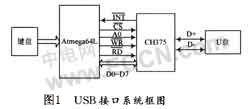
When CH375 works in host mode, MCU completes communication with CFl375 through comprehensive control of RD, WR, chip select CS, interrupt INT and address line AO, and realizes the function of reading and writing data from USB disk through USB interface. INT pin is connected to external interrupt input pin of MCU. When USB disk is inserted, INT becomes low level to trigger external interrupt. When CS, RD and AO are all low level, data in CH375 can be output through D7~DO; when CS, WR and AO are all low level, data on D7~DO is written into CH375 chip; when CS and WR are all low level and AO is high level, data in D7-DO can be written into CH375 chip as command code.
2.2 Connection between MP3 decoding chip and MCU
VSl003 transmits commands and data with ATmega64L through synchronous serial bus SPI. Since ATmega64L has internal integrated SPI bus module, SPL can be easily controlled as long as SPI related registers are written correctly. This hardware SPI bus reduces the difficulty of software design. The SPI interface of VSl003 has two working modes: new mode and compatible mode. Set register SM_SDI. NEW is 1 to put VSl003 in new mode. At this time, set SMSDISFIARED to 0. The transmission of control signals and data signals will use xCS and xDCS as synchronization signals respectively.
After the system starts, the MCU controls the code stream information of the songs stored in the USB flash drive to the VSl003 chip. Through the decoding of the VSl003 chip and its high-quality stereo DAC and headphone drive circuit, the MP3 song playback function is realized. Under the control of the button, the song playback mode and song selection functions are realized.
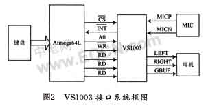
All data and control commands of VSl003 are realized through the SPI bus interface, so the interface with the MCU is relatively simple, including 3 SPI data lines and 4 control lines connected to the PB4~PB7 pins. The interface block diagram is shown in Figure 2.
3 Software Programming
3.1 U disk file management system
The file system used by the U disk is generally the FAT file system. It divides the storage space into 5 parts: Master Boot Sector (MBR), DOS Boot Area (DBR), File Allocation Table (FAT), File Directory Table (FDT) and Data. Ctt375 provides a U disk file-level subroutine library, and the microcontroller can directly call the subroutine to read and write file data in the U disk.
3.2 Reading USB data
The program for reading and writing USB flash drives in the application of the microcontroller can be divided into two parts: application program and firmware program. The application program completes the system's data processing tasks, peripheral control and other functions; the firmware program handles the underlying USB communication protocol, file system, reliable data transmission on the USB bus and access operations on the USB flash drive. CH375 has built-in firmware for processing the dedicated communication protocol of mass storage devices, so the microcontroller of the embedded system can use the USB flash drive as a removable large-capacity storage device through CH375. Data reading and writing only requires a few instructions, and there is no need to understand the USB communication protocol in detail. [page] The reading
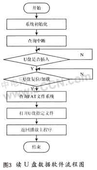
and writing method of the USB flash drive file adopts the sector mode, which uses sectors (each sector is usually 512 bytes) as the basic unit for reading and writing operations, thereby simplifying the USB storage device into an external data storage device. The microcontroller can freely read and write data in the USB storage device and can also freely define its data structure. In this article, the communication between the microcontroller and the USB flash drive is carried out in the form of query interrupt response. The specific flow chart is shown in Figure 3.
Use AVR programming tool software ICCAVR to write system C program. CH375 provides packaged library function CH375HF6.LIB, which contains a large number of macro definitions to facilitate programming.
Here are some key operation functions of CH375: CH375 initialization function CH375Liblnit(); query whether the USB disk is ready function CH375DiskReady(); query disk information function CH375DiskQuery(); open the file or directory with the specified name CH375FileOpen(); CH375FileCreate() is to create a new file and open it. If the file already exists, delete it first and then create it; CH375FileClose() is to close the current file; CH375FileReadX() reads data from the current file in units of sectors, and CH375FileWriteX() writes data to the current file in units of sectors.
3.3 VSl003 control protocol
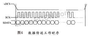
VSl003 communicates data and control information with the host through an SPI serial bus working in slave mode. The transmission of control signals and data signals uses xCS and xDCS as synchronization signals respectively. When the data signal xDCS is low, the audio data is transmitted through the serial interface. When the control signal xCS is low, the control command is transmitted through the serial interface. The control command is always 16 bits. The control of VSl003 is realized by reading/writing different registers. As a slave working mode, VSl003 indicates whether the host is allowed to transmit data through a signal line DREQ. When DREQ is high, VSl003 can accept at least 32 kB of data or control commands.
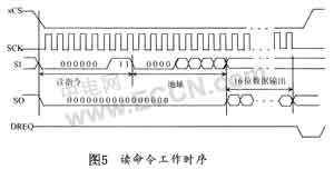
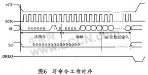
The following introduces the implementation of the VSl003 communication protocol in the new mode and when SM-SDISHARE is set to 0. Figure 4 describes the working sequence of data transmission. It uses xDCS as the synchronization signal. As the clock signal changes, the data is sent out from the high or low bit in turn according to the setting of the control command. The control command protocol includes 1 control instruction byte, 1 address byte and 1 16-bit data word. Each read and write control can operate 1 register. The read command and write command are Ox03 and Ox02 respectively. The working sequence of these two control commands is shown in Figure 5 and Figure 6 respectively.
3.4 Playing MP3 files
First, complete the initialization of VSl003 and SPI bus, then wait for the system to open the MP3 file from the U disk storage medium, and put the data of a sector read from it into the 512 B buffer of Atmeag64L, and then send the data to VSl003, and the decoding chip will automatically play smooth music. Since VSl003 has a 32 B data buffer, 32 B data can be sent to it at a time and then the DREQ pin is checked. When DREQ is high, the next 32 B data is sent. After sending the content of a sector, the next sector content will continue to be read from the U disk, and the operation is repeated until the file is played.
4 Conclusion
After the system C program is successfully compiled through ICCAVR, a HEX executable file is generated. Then, the compiled executable file is downloaded to the target board using the JTAG interface in the AVRStudio compiler. When the U disk is inserted into the system, the MP3 music in the U disk will be played, and the sound quality and playback continuity are very good. This solution can effectively identify and read USB flash drives, breaking through the limitation of the integration of decoder and memory in MP3 players. The storage capacity can be increased on the basis of the original hardware by simply using a larger capacity USB flash drive. It has good application prospects in audio, automotive electronics and data acquisition and storage.
Previous article:AVR single chip microcomputer hardware circuit design
Next article:Comparison of the application of reactive power compensation automatic control schemes in power design
Recommended ReadingLatest update time:2024-11-16 21:35

- Popular Resources
- Popular amplifiers
 Professor at Beihang University, dedicated to promoting microcontrollers and embedded systems for over 20 years.
- Innolux's intelligent steer-by-wire solution makes cars smarter and safer
- 8051 MCU - Parity Check
- How to efficiently balance the sensitivity of tactile sensing interfaces
- What should I do if the servo motor shakes? What causes the servo motor to shake quickly?
- 【Brushless Motor】Analysis of three-phase BLDC motor and sharing of two popular development boards
- Midea Industrial Technology's subsidiaries Clou Electronics and Hekang New Energy jointly appeared at the Munich Battery Energy Storage Exhibition and Solar Energy Exhibition
- Guoxin Sichen | Application of ferroelectric memory PB85RS2MC in power battery management, with a capacity of 2M
- Analysis of common faults of frequency converter
- In a head-on competition with Qualcomm, what kind of cockpit products has Intel come up with?
- Dalian Rongke's all-vanadium liquid flow battery energy storage equipment industrialization project has entered the sprint stage before production
- Allegro MicroSystems Introduces Advanced Magnetic and Inductive Position Sensing Solutions at Electronica 2024
- Car key in the left hand, liveness detection radar in the right hand, UWB is imperative for cars!
- After a decade of rapid development, domestic CIS has entered the market
- Aegis Dagger Battery + Thor EM-i Super Hybrid, Geely New Energy has thrown out two "king bombs"
- A brief discussion on functional safety - fault, error, and failure
- In the smart car 2.0 cycle, these core industry chains are facing major opportunities!
- The United States and Japan are developing new batteries. CATL faces challenges? How should China's new energy battery industry respond?
- Murata launches high-precision 6-axis inertial sensor for automobiles
- Ford patents pre-charge alarm to help save costs and respond to emergencies
- New real-time microcontroller system from Texas Instruments enables smarter processing in automotive and industrial applications
- Analysis of Capacitance and Resistance Changes Caused by PCB Layout
- LSM6DS3 calibration issue
- F28335 ADC learning process
- About the fabrication process of fiber-embedded microfluidic chips
- Apply for a free trial! Fluke Norma6000 Power Analyzer, born for convenience!
- Chupuyuan 60MHz bandwidth LCD digital oscilloscope
- [GD32E503 Review]——step04. Domestic M33 for uCgui transplantation
- (Transfer) Ultra-low power consumption 4G module G8100 module data free sharing including schematic diagram
- Analysis of the BUCK/BOOST circuit principle, the summary is so perfect!
- Necessity and Principle of DSP Simulator

 Altium Designer schematic library CH375.SchLib
 CH375_CH376_U disk module
 STM32 processor development and application based on MDK


 京公网安备 11010802033920号