Single-chip microcomputers are small, flexible, and easy to expand into powerful control systems. At present, some monitoring terminals and many independent control systems (such as: microcomputer excitation devices of generators) are mostly composed of single-chip microcomputers as the core. However, due to reasons such as harsh working environment and electromagnetic interference, even if a single-chip microcomputer designed according to the requirements of the industrial measurement and control environment is used, it is difficult to ensure that the control system can operate reliably for a long time, which leads to the paralysis of the control system. In this way, how to improve the reliability of the control system and ensure that the measurement and control system can operate correctly and stably is particularly important. Obviously, the use of dual CPU redundant design is a very effective solution. Due to the powerful functions and low price of single-chip microcomputers, it provides good conditions for the design of dual-machine redundant systems. To this end, we designed a dual-machine fault-tolerant system consisting of two single-chip microcomputers, which realized the mutual backup and mutual switching of the dual machines with a relatively simple design method that is completely different from the traditional multi-CPU system. In the design of this dual-machine redundant system, the key issues are the reconstruction strategy of the dual-machine system and the arbitration logic switching of the dual-machine system.
1 Traditional multi-CPU system design method
There are three common design methods for traditional multi-CPU systems:
① Use dual-port RAM to realize communication between CPUs. Dual-port RAM is a high-speed parallel transmission chip with two sets of I/O ports and competition arbitration circuits. It can connect two CPUs at the same time. In this way, communication between multiple CPUs can be realized through dual-port RAM.
② Use shared memory to achieve communication between CPUs. This method is similar to the previous method, but the difference is that the previous method uses the competition arbitration circuit of the dual-port RAM to achieve access to the RAM, while this method uses different timings to achieve memory sharing.
③ Use bus method to realize communication between CPUs. Communication between CPUs is realized through interface chips or interfaces such as SPI, I2C and SMBus of the CPU itself.
2 Structure and working principle of the dual CPU system
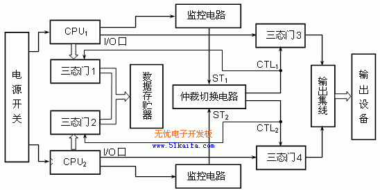
The dual-CPU control system is completely different from the traditional multi-CPU system design method. It is composed of two AT89C51 CPUs produced by Atmel. The two machines serve as backup for each other, run independently and in parallel, and switch hard logic. The principle block diagram of the dual-CPU control system is shown in Figure 1.
This is a non-voting dual-machine redundant system, where one CPU serves as a hot backup for the other CPU, and the two machines run synchronously on tasks. All input signals are sent to both CPUs through the input interface at the same time, but the output after CPU calculation and processing is controlled by the arbitration switching circuit. Only the main CPU is allowed to read and write external data storage and output to external devices. When the main CPU fails, the system's self-detection switching logic will send a signal to automatically cut off its output channel and alarm through the CPU's working indication system. At this time, the system automatically or manually switches to another backup CPU and opens its output channel at the same time. The backup machine becomes the main machine running state, and the control system is downgraded to single machine operation. People can unplug the original host from the system for maintenance. As can be seen from the figure, the address, data and control buses of the two CPUs are connected to the external data storage through a group of three-state gates (three-state gates 1 and 2) outputs, and some output control I/O ports of the two CPUs are connected to the external output control device through another group of three-state gates (three-state gates 3 and 4) outputs. The control ends of the two groups of three-state gates are simultaneously controlled by the arbitration switching circuit, and the two outputs of the arbitration switching circuit are mutually inversely logical, that is, only one output can make the corresponding three-state gate (such as three-state gates 1 and 3) output normally, and the other output makes the corresponding three-state gate (such as three-state gates 2 and 4) in a high-impedance state, thereby not affecting the normal reading and writing of data by the main CPU and the output of data to the control I/O port.

Figure 1 Schematic diagram of dual CPU control system
|
Table 1 Truth table of dual-machine arbitration switching logic
[page] |
3 Dual-machine arbitration switching logic circuit
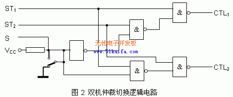
In this dual CPU control system, the two CPUs are hot backups for each other and run at the same time, one is the host and the other is the backup. When both CPUs are running normally, the system defaults CPU1 as the host and CPU2 as the backup. When the host fails, the system is required to automatically switch to the backup so that the backup becomes the host, thereby replacing the original host and continuously running from the fault location and sending an alarm signal. At the same time, it is required to be able to manually select the host to run through a manual switch. Let the signals for judging whether the two CPUs are working normally be ST1 and ST2 respectively. When working normally, their states are 1, and when working abnormally, their states are 0. The control end whose arbitration switching circuit output is 0 controls the corresponding three-state gate group of the CPU that is working normally to enable, and the control end whose arbitration switching circuit output is 1 controls the corresponding three-state gate group of the other CPU to prohibit output. The control switch for automatically or manually selecting the host is S. When both CPUs are working properly, the S switch can automatically select or specify the host (when the S switch state is 1, CPU1 is automatically defaulted as the host, and when the S switch state is 0, CPU2 is forced to be the host); when any of the two CPUs is not working properly, it is irrelevant to the state of the S switch at this time. The output of the arbitration switching circuit can ensure that only the enable end of the three-state gate group connected to the normal CPU is 0, thereby controlling the normal CPU to read and write data and output control normally; when both CPUs are not normal, the two outputs of the arbitration switching circuit are 1, and both CPUs cannot read and write data and output control normally. In this way, when any one or all of the two CPUs are normal, it can be guaranteed that only one CPU can read and write data and output control normally. When both CPUs are not normal, the system cannot work normally. The truth table obtained as required is shown in Table 1.
From the truth table, we can get the control signal logic CTL1 and CTL2 of the two control tri-state gates of the arbitration switching circuit respectively:
 ,
,
The constructed arbitration switching circuit is shown in FIG2 .

4 CPU status monitoring circuit

The monitoring circuit uses a microprocessor chip MAX813L with power monitoring circuit and watchdog function. This chip has 4 functions:
① Watchdog timer function. When the watchdog input signal does not change within 1.6s, a watchdog output is generated;
② Voltage monitoring function. When the power is off or the power monitoring voltage is lower than 1.25V, a power-off output is generated;
③ Power-on reset function. Automatically generates a reset signal with a pulse width of 200ms when powered on;
④ Manual reset function: When the manual reset terminal inputs a low level, a reset signal is generated and output.
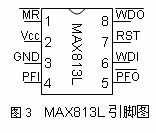
MAX813L uses DIP-8 package, as shown in Figure 3, the pin functions are as follows:
① MR: Manual reset input terminal, which can be connected to a manual reset button. If the input low level is maintained for more than 140ms, a reset (RST) signal can be generated;
② Vcc: +5v power supply;
③ GND: power ground;
④ PFI: power detection input terminal;
⑤ PFO: power supply detection output terminal, maintains high level when the power supply is normal;
⑥ WDI: Watchdog input terminal. Commonly known as the "feed the dog" signal, the terminal must input a reverse signal within 1.6s;
⑦ RST: reset output terminal. High level is effective, and can output a positive pulse of 200ms. When the power supply Vcc is lower than 4.65v, RST maintains a high level;
⑧ WDO: Watchdog output terminal. It outputs high level in normal operation. When the WDI signal cannot be sent in time and reverses within 1.6s, this terminal outputs low level signal.
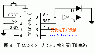
Since AT89C51 does not have a watchdog function, in order to monitor the system status, the watchdog timer function of MAX813L is mainly used in this system. The watchdog input terminal WDI is provided by P3.4 of the CPU. The CPU changes P3.4 regularly within the specified time.
The watchdog output terminal WDO provides the current CPU status signal to the STi (i = 1 or 2) terminal of the arbitration switching circuit, so that the arbitration switching circuit automatically or manually determines the host. Figure 4 shows the watchdog circuit connected to CPU1 using MAX813L. When CPU1 works normally and can provide P3.4 signal normally, WDO terminal ST1 outputs high level, D1 is on and D2 is off; when CPU1 works abnormally and cannot provide P3.4 signal normally, WDO terminal ST1 outputs low level, D2 is on and D1 is off. [page]

5 System Hardware Circuit
Figure 5 shows a hardware circuit composed of the dual CPU switching and control system introduced in this article. As can be seen from the figure, each CPU in the system can communicate with the host computer through the RS232 serial port, and the two CPUs run independently of each other, sharing the external 16KB RAM and controlling the 8-way I/O port output through the dual-machine arbitration switching logic circuit. This method can also be used to form a larger capacity (maximum 64KB) external RAM and more output control I/O ports or expand I/O ports by adding three-state gates.

Figure 5 A hardware circuit of a dual CPU switching and control system
6 Conclusion
The dual CPU control system has a unique design. The two CPUs run independently of each other, but they read and write data from the same external RAM. Only the main CPU can actually read and write data, so there is no problem of memory data exchange and sharing. At the same time, only the main CPU can output and control external devices. It can be widely used in occasions requiring high-reliability control. The author applied this technology to the computer sample cutting machine developed by himself and achieved satisfactory results.
Previous article:Design of single chip microcomputer for sending and receiving short messages
Next article:Design of automatic control system for ironing machine based on single chip microcomputer
Recommended ReadingLatest update time:2024-11-16 17:56


- Popular Resources
- Popular amplifiers
-
 西门子S7-12001500 PLC SCL语言编程从入门到精通 (北岛李工)
 -
 Siemens Motion Control Technology and Engineering Applications (Tongxue, edited by Wu Xiaojun)
 -
 MCU C language programming and Proteus simulation technology (Xu Aijun)
 -
 100 Examples of Microcontroller C Language Applications (with CD-ROM, 3rd Edition) (Wang Huiliang, Wang Dongfeng, Dong Guanqiang)
 Professor at Beihang University, dedicated to promoting microcontrollers and embedded systems for over 20 years.
- Innolux's intelligent steer-by-wire solution makes cars smarter and safer
- 8051 MCU - Parity Check
- How to efficiently balance the sensitivity of tactile sensing interfaces
- What should I do if the servo motor shakes? What causes the servo motor to shake quickly?
- 【Brushless Motor】Analysis of three-phase BLDC motor and sharing of two popular development boards
- Midea Industrial Technology's subsidiaries Clou Electronics and Hekang New Energy jointly appeared at the Munich Battery Energy Storage Exhibition and Solar Energy Exhibition
- Guoxin Sichen | Application of ferroelectric memory PB85RS2MC in power battery management, with a capacity of 2M
- Analysis of common faults of frequency converter
- In a head-on competition with Qualcomm, what kind of cockpit products has Intel come up with?
- Dalian Rongke's all-vanadium liquid flow battery energy storage equipment industrialization project has entered the sprint stage before production
- Allegro MicroSystems Introduces Advanced Magnetic and Inductive Position Sensing Solutions at Electronica 2024
- Car key in the left hand, liveness detection radar in the right hand, UWB is imperative for cars!
- After a decade of rapid development, domestic CIS has entered the market
- Aegis Dagger Battery + Thor EM-i Super Hybrid, Geely New Energy has thrown out two "king bombs"
- A brief discussion on functional safety - fault, error, and failure
- In the smart car 2.0 cycle, these core industry chains are facing major opportunities!
- The United States and Japan are developing new batteries. CATL faces challenges? How should China's new energy battery industry respond?
- Murata launches high-precision 6-axis inertial sensor for automobiles
- Ford patents pre-charge alarm to help save costs and respond to emergencies
- New real-time microcontroller system from Texas Instruments enables smarter processing in automotive and industrial applications
- Help, where can I find a high frequency magnetic core that supports 300MHz
- LSM303AH Code and PCB Library
- [ATmega4809 Curiosity Nano Review] Unboxing
- [CY8CKIT-149 PSoC 4100S Review] + Use of Timer/Counter
- The register value returned by the lis25ba operation is incorrect
- MOSFET data sheet, try looking at it this way!
- Software Development (Part-time)
- About the frequency signal source
- MSP430 G2553 Timer/Counter Timer_A
- DSP28027 SPI learning

 西门子S7-12001500 PLC SCL语言编程从入门到精通 (北岛李工)


 京公网安备 11010802033920号