1 Controller Working Principle
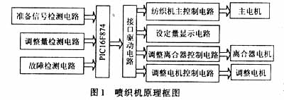
The adjustable elastic band controller includes a fixed plate, two left and right horizontal bolt holes are arranged in the fixed plate, a latch part is arranged in front of the fixed plate, the latch part includes a hook arm and a base, the hook arm and the base form a notch, a cantilever and a fixed arm are contained in the notch, the right end of the cantilever is pivotally connected with the right end of the fixed arm by bolts, a rectangular block is arranged at the left end of the cantilever, two parallel longitudinal bolt holes are arranged in the rectangular block, a connecting seat is arranged in front of the rectangular block, the connecting seat is fixed in front of the rectangular block, a pair of rollers and two guide rods are arranged at the left end of the connecting seat, and the hook arm is also provided with a clamping wheel for fixing the cantilever. The principle block diagram of the controller is shown in Figure 1.

When the textile machine is operating normally, the adjustment clutch is in a reliable separation state under the control of the single-chip computer PIC16F874. When the machine needs to be restarted after being shut down for some reason, press the adjustment button, and the system sends an adjustment signal to make the adjustment clutch control circuit work, and the adjustment clutch is in an engaged state. At this time, the adjustment motor rotates forward, reverse, forward and reverse, and counter-rotate under the control of the system, and adjusts the tightness of the weft to make it appropriately dense. After the adjustment is completed, the adjustment clutch returns to the separation state and displays the end signal of the tension adjustment.
2 Hardware Circuit Design
According to the function of the system, reliable control is the premise and accuracy is the key. The hardware strives to have a simple structure to improve reliability, while accuracy is guaranteed by precise speed change mechanism and detection circuit. Part of the hardware circuit is shown in Figure 2.
 [page]
2.1 MCU Selection
Since the system requires high adjustment accuracy, it is easy to set the adjustment amount and can protect against power failure. PIC16F874 contains 10b A/D conversion, high speed and low price. It has 128B electrically erasable E2PROM memory, which can easily write the adjustment amount for later use. 16F874 also has a watchdog to ensure the reliability of system program operation. At the same time, the synchronous serial module (SSP) lays the foundation for networking with industrial computers in the future.
2.2 Detection Circuit
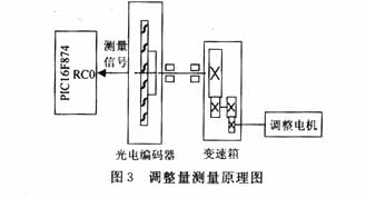
The detection part mainly completes the detection of the clutch state and textile machine, and uses a photoelectric encoder to improve the detection accuracy. In order to ensure the safety of the MCU, all detection signals are connected to the MCU through an optical coupler. The circuit is shown in Figure 2.
2.3 Adjustment amount setting and display
In order to improve the adjustment accuracy, the following measures are taken: adopting a precise gear reduction mechanism; increasing the operating frequency of PIC16F74 to 20 MHz, and the execution time of an instruction is only 1μs, thereby improving the adjustment accuracy. As shown in Figure 3. RD0~RD6 of the microcontroller is used as the digital tube segment selection signal, RE0~RE2 is used as the digital tube chip selection signal, DS1 is used to display forward, reverse, forward and reverse, and reverse; DS2, DS3 display the set adjustment amount.


2.4 Control Circuit
The control of the system includes main motor locking, clutch motor, and adjustment motor. They are controlled by the output of the single-chip I/O ports RA0, RA1, RA2, and RA3. In order to ensure the safety of the single-chip, all output control signals are isolated by optical coupling, amplified by transistors, and driven by control relays and field effect transistors, so that the textile machine can achieve fast and reliable control.
3 Software Design
In the software design, a modular structure is adopted. The whole program consists of the main program and various functional subroutines and interrupt service programs. The system software flow chart is shown in Figure 4, which mainly includes initialization adjustment amount setting, display, detection and control of the working state of the clutch, and adjustment of the motor working state control.
The system has a simple structure, stable and reliable operation, high control accuracy, perfect protection function, and leaves certain resources for future technical improvements. It is low-cost and has received good feedback from users. It has laid a solid foundation for the future mechanical textile industry, allowing the speed of textile production to increase and the efficiency of production to be accelerated.
References:
[1]. PIC16F874 datasheet http://www.dzsc.com/datasheet/PIC16F874_4.html.
[2]. PIC16F74 datasheet http://www.dzsc.com/datasheet/PIC16F74_861.html.
[3]. DS1 datasheet http://www.dzsc.com/datasheet/DS1_1106249.html.
Previous article:Analysis and Research on BANK and PAGE in PIC Microcontroller
Next article:A brief discussion on PIC microcontroller software development skills
 Professor at Beihang University, dedicated to promoting microcontrollers and embedded systems for over 20 years.
- Innolux's intelligent steer-by-wire solution makes cars smarter and safer
- 8051 MCU - Parity Check
- How to efficiently balance the sensitivity of tactile sensing interfaces
- What should I do if the servo motor shakes? What causes the servo motor to shake quickly?
- 【Brushless Motor】Analysis of three-phase BLDC motor and sharing of two popular development boards
- Midea Industrial Technology's subsidiaries Clou Electronics and Hekang New Energy jointly appeared at the Munich Battery Energy Storage Exhibition and Solar Energy Exhibition
- Guoxin Sichen | Application of ferroelectric memory PB85RS2MC in power battery management, with a capacity of 2M
- Analysis of common faults of frequency converter
- In a head-on competition with Qualcomm, what kind of cockpit products has Intel come up with?
- Dalian Rongke's all-vanadium liquid flow battery energy storage equipment industrialization project has entered the sprint stage before production
- Allegro MicroSystems Introduces Advanced Magnetic and Inductive Position Sensing Solutions at Electronica 2024
- Car key in the left hand, liveness detection radar in the right hand, UWB is imperative for cars!
- After a decade of rapid development, domestic CIS has entered the market
- Aegis Dagger Battery + Thor EM-i Super Hybrid, Geely New Energy has thrown out two "king bombs"
- A brief discussion on functional safety - fault, error, and failure
- In the smart car 2.0 cycle, these core industry chains are facing major opportunities!
- The United States and Japan are developing new batteries. CATL faces challenges? How should China's new energy battery industry respond?
- Murata launches high-precision 6-axis inertial sensor for automobiles
- Ford patents pre-charge alarm to help save costs and respond to emergencies
- New real-time microcontroller system from Texas Instruments enables smarter processing in automotive and industrial applications
- Homemade Raspberry Pi 3 board 12 times bigger, and it works
- Learn 5 key technical points about TI BAW technology
- Procurement of ADI
- GD32L233C-START Development Board Study Notes (Part 2)
- Evaluation board EasyARM-RT1052 data
- President of the Chinese Academy of Sciences: Turn the US bottleneck list into a scientific research list
- Siemens Industrial Automation Data Collection (August 9, 2019)
- The troubles of capacitor testers in traditional mode - Part 1
- Playing with Zynq Serial 19——[ex02] A happy running water lamp based on Zynq PL
- 5G O-RAN All-in-one Small Base Station Hardware White Box Reference Architecture

 Design paper of dot matrix electronic display screen
 *** *** *** *** *** *** ***** ** Two wire/I2C Bus READ/WRITE Sample Routines of Microchip s ** 2
 TC913AIJA


 京公网安备 11010802033920号