The serial port of the microcontroller is very useful. Through it, we can transmit the data of the microcontroller system back to the computer for processing or receive data from the computer and perform corresponding actions. Now I will introduce to you the computer's RS-232 interface and the microcontroller serial communication program design method. There are many such articles on www.51hei.com, so you can search for them.
Introduction to RS-232:
In serial communication, both parties are required to use a standard interface so that different devices can be easily connected for communication. RS-232-C interface (also known as EIA RS-232-C) is currently the most commonly used serial communication interface. (The "-C" in "RS-232-C" just means the version of RS-232, so it is the same as the abbreviation "RS-232") It was a standard for serial communication jointly formulated by the American Electronics Industry Association (EIA) in 1970, the Bell System, modem manufacturers and computer terminal manufacturers. Its full name is "Technical Standard for Serial Binary Data Exchange Interface between Data Terminal Equipment (DTE) and Data Communication Equipment (DCE)". The standard stipulates the use of a 25-pin DB-25 connector, specifies the signal content of each pin of the connector, and also specifies the levels of various signals. Later, IBM's PC simplified RS232 into a DB-9 connector, which became the de facto standard. The RS-232 port of industrial control generally only uses three lines: RXD, TXD, and GND.
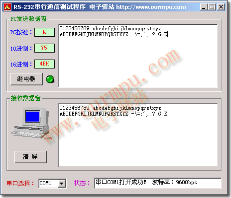
Next, let's use the S51 enhanced single-chip microcomputer experiment board to develop a simple serial communication experiment program. This is a comprehensive serial communication experiment that requires the relevant accessories of the full package customer to complete. Through this experimental program, we can detect the status of the serial port of the experimental board, receive data sent by the computer, and then send it back to the computer. If the characters displayed in the sending and receiving windows in the program are the same, it means that the serial port of the experimental board is good and can send and receive data normally. In addition, the microcontroller receives the control instructions of the computer and controls the action of the relay on the experimental board according to the control instructions.  First, let's take a look at the actual effect of the communication software we made. . .
|
The interface between RS-232 interface and single-chip microcomputer serial communication program design | ||
|
|
 |
|
|
Figure 1 |
||
|
Note: Current key: "K", key ASC code: "75", key hexadecimal code: "4BH" |
||
|
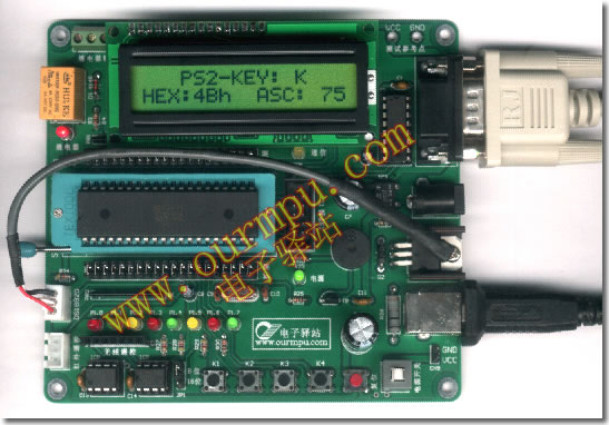
The effect diagram of the S51 enhanced single-chip microcomputer experimental board and the computer serial port realizing RS232 communication operation | ||
|
|
 |
|
|
Figure 2 |
||
| Note: Press the "K" key on the PC keyboard and the MCU will display the key received by the serial port on the LCD module in real time (the size keys are locked). 1. The first line of the LCD module displays "PS2-KEY: K", indicating that the PS2 keyboard key is received: "K" 2. The second line of the LCD module displays "HEX: 4Bh ASC: 75", indicating that the HEX code of K is "4BH" and the ASC code is: "75" |
||
 |
||
|
Figure 3 |
||
|
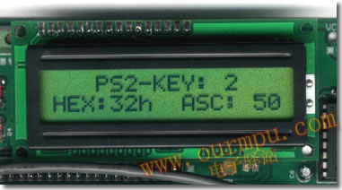
Note: Press the "2" key on the PC keyboard and the MCU will display the key received by the serial port on the LCD module in real time. 1. The second line of the LCD module displays "HEX: 32h ASC: 50", indicating that the HEX code of K is "32H" and the ASC code is: "50". 2. The first line of the LCD module displays "PS2-KEY: 2", indicating that the key received from the PS2 keyboard is: "2". |
||
As you can see from the two pictures above, our main goals are as follows:
1. On the computer, the communication test program written in VB6.0 detects the keyboard operation, and displays the pressed PS2 keyboard (PC keyboard) keys in the data sending window, showing the current key, the ASC code of the key, and the hexadecimal code of the key. At the same time, the key value is sent to the S51 microcontroller experiment board through the computer's RS-232 serial port. After the AT89S51 microcontroller on the experiment board receives the data, it is displayed in binary on the 8-bit high-brightness LED of the experiment board, and then the received data is resent back to the computer's RS-232 serial port. After the computer receives it, it is displayed in the program's receiving data window.
2. The single-chip microcomputer detects and identifies the keyboard key value sent by the computer, and displays the key value in binary form on the 8-bit high-brightness LED of the P1 port. At the same time, the current key, the key's HEX code, and the ASC code are displayed in real time on the 1602 LCD module.
3. The MCU receives the control instructions from the computer. When the computer sends the "relay ON instruction", the MCU drives the relay on the experimental board to close. On the contrary, if the computer sends the "relay OFF instruction", the MCU drives the relay to release. We can learn and master the principle of computer intelligent control. As long as we master this method, it will not be difficult for us to control the electrical switches at home by simply clicking the mouse on the computer (operation method, click the "relay" button of the software, the relay on the experimental board will close, click the button again, and the relay will release). [page]
4. After the MCU receives the data, it will issue a short sound prompt. At the same time, the data will be resent back to the computer serial port for the computer program to receive and display. After the computer software receives the data sent by the MCU, it will be displayed in the software's receiving data window.
【RS-232 interface and single-chip microcomputer serial communication program design】
The system program consists of single-chip microcomputer communication program and computer communication program. In the microcomputer measurement and control system, the computer is generally called the host computer, and the single-chip microcomputer system for front-end acquisition control is called the lower computer. The host computer is mainly responsible for the comprehensive management of all measurement and control data and the scheduling control of the lower computer, while the lower computer is composed of a single-chip microcomputer as the front-end measurement and control system, which collects raw data and controls equipment. The lower computer is managed and controlled by the host computer.
1. Single-chip microcomputer program development
51 single-chip microcomputer has a full-duplex serial communication port, which is very suitable for communicating with computers. The serial port development of 51 single-chip microcomputers is introduced in detail in various textbooks. We will not repeat it here. You can refer to the books. The main functions of the single-chip microcomputer program are as follows: initialize the serial port, open the serial port interrupt, receive data sent by the computer, display data on the 1602 LCD module, send data back to the computer RS-232 serial port, receive relay control commands, control relay actions, etc.
The reference program for microcontroller communication is as follows:
ORG 0000H
AJMP START ; Go to the initialization program
ORG 0023H
AJMP PGUART ; Go to the serial interrupt service subroutine
START: MOV SP,#60H ; stack pointer initialization
MOV P0,#0FFH ; P0 port initialization
MOV P1,#0FFH ; P1 port initialization
MOV P2,#0FFH ; P2 port initialization
MOV P3,#0FFH ; P3 port initialization
MOV TMOD,#20H ; timer T1 works in mode 2, automatic reload
MOV TH1,#0FDH ; TH1 initial value is "0FDH", 9600bps
MOV TL1,#0FDH ; TL1 initial value is "0FDH", 9600bps
MOV SCON,#50H ; serial port works in mode 1, allow reception
SETB TR1 ; start timer T1
SETB ES ; allow serial port interrupt
SETB EA ; open total interrupt
CLR UABIT
; ---------------------- RS-232 interface and microcontroller serial communication program design -------------------------------
MAIN: ...... ; The main program handles other tasks and waits for the serial port interrupt
AJMP MAIN
PGUART: ......;Serial port interrupt service subroutine, receive and process data
RETI
END
2. RS-232 serial communication test software development
Computer RS-232 serial communication test software is developed using VB6.0. VisualBasic 6.0 (VB6.0 for short) is easy to learn.
VB6.0 is a visual programming development software. The development program is simple and easy to learn. VB program development is mainly divided into two steps: the first step is to use VB controls to design the software interface, and the second step is to write corresponding execution program codes for various controls. After the code is written, it can be run to view the results.
VB6 provides a variety of controls, among which MSCOMM.OCX is a control for serial communication. We can add this control to the Toolbox, so that we can use this control to design serial communication programs.
The following introduces the main properties and methods of the Mscomm control:
1) CommPort: Set or return the serial port number. The value range of VB6 is 1 to 16, which means opening or returning the communication port number COM1 to COM16
2) Setting: Set or return the baud rate, parity bit, data bit, and stop bit of the serial port. For example: Mscomm1.Setting="9600, N, 8, 1"
3) PortOpen: Open or close the serial port, the format is: Mscomm1.PortOpen=『True/False』
4) InBufferSize: Sets or returns the size of the receive buffer, the default is 1024 bytes
5) InBufferCount: Returns the number of bytes waiting to be read in the receive buffer. The receive buffer can be cleared by setting this property to 0
6) RThreshold: This property is a threshold. When the number of bytes in the receive buffer reaches or exceeds this value, an OnComm event is generated
7) InputLen: Sets or returns the number of bytes read in the receive buffer using Input. If it is 0, Input will read all the contents of the entire buffer.
8) Input: This property represents InputLen characters from the receive buffer.
9) OutBufferSize: Sets or returns the send buffer size, the default is 512 bytes.
10) OutBufferCounter: Returns the number of characters waiting to be sent in the send buffer, which can be used to clear the buffer.
11) Output: Send a string to the send buffer, that is, send data to the serial port.
Step 1: Develop the program interface.
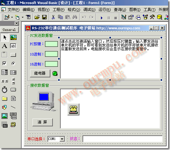
Open VB6.0 -> Create a new "Standard EXE" project. Add various buttons and controls we want to use in the project window Form1. One of the controls with an icon like a phone is the MSCOMM serial communication control. This control is visible when designing the interface, but not when the program is running. Finally, after placing various controls, the program interface will appear. Isn't it very simple? As shown in Figure 4 below:
|
RS-232 serial communication test software interface development | ||
|
|
 |
|
|
Figure 4[page] |
||
Step 2: VB software writing
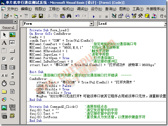
When the software interface design is completed, we can add code to the program. The main functions implemented in the program are as follows: RS-232 port initialization, detection of keys pressed on the PC keyboard, sending key codes, displaying the current key codes in the data sending window, receiving and displaying the data sent by the microcontroller in the receiving data window, detecting the operation of the relay control button, and sending relay control commands. . . As shown in Figure 5 below:
|
RS-232 serial communication test software program code writing | ||
|
|
 |
|
|
Figure 5 |
||
[Serial communication experiment operation]
After completing the single-chip microcomputer communication program and the VB program development on the PC, we compile the project and get the HEX format target file rs232test.hex and the serial port test program executable file RS232test.exe for the single-chip microcomputer chip. Then we can take out the experimental board and immediately conduct the serial port communication experiment to test our actual communication effect.
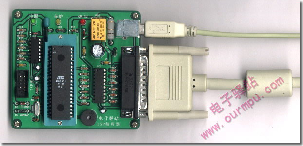
1. Use the ISP programmer to burn the target file rs232test.hex into the AT89S51 single-chip microcomputer (see Figure 6 below)
 |
|
|
2. As shown in Figure 2 above: we lock the AT89S51 chip with the communication program burned into the S51 microcontroller experiment board, and then insert the 1602 character LCD module into the 1602 interface of the experiment board, connect the experiment board and the computer with the RS232 serial communication cable and USB cable, press the power switch of the experiment board, turn on the power, and the power indicator on the experiment board lights up. The experiment board is ready to receive data sent by the computer at any time.
3. Double-click the serial port test program RS232test.exe we wrote to start the RS-232 serial communication test software, set the communication port connected to the experiment board in the software, and then click "PC Send Data Send Window" to activate the input window, and then we press the keys on the computer keyboard. Pressing the keys on the PS2 keyboard will be displayed in the software and sent to the microcontroller for display through the 1602 LCD module. When the correct data is received, the buzzer on the experiment board will also emit a short sound, so that the feeling of pressing the keyboard is reflected in the sound. After the data sent back from the MCU is received by the software, it will be restored and displayed in the Send Data Window. If the keys we press on the keyboard on the computer are the same in the Send Window, Receive Window of the software and the 1602 LCD module on the experimental board, it means that the RS-232 serial port of our computer is good, the serial port of the MCU is also good, and the communication is normal. Then, we can click the "Relay" button in the software. After the MCU on the experimental board receives the control command from the computer, it will control the relay to produce the corresponding switch action, so as to realize the control of the relay on the experimental board by the computer software.
Deepen the understanding of the 51 MCU serial port through experiments:
Let's do an additional experiment through this set of serial port test programs. In theory, when we press the keys on the keyboard, all the keys will be sent to the MCU, and then returned to the computer. The number and characters displayed in the PC Send Data Window and Receive Data Window on the serial port test software should be exactly the same, as shown in Figure 1 above. However, when we press the PC keyboard quickly and continuously (note: the continuous speed must be fast enough to see the experimental phenomenon), we will find that characters are sometimes missed in the receiving data window. Cumulatively, the characters in the receiving window will be less than those in the sending window.
What is the reason for this phenomenon? !
In fact, this is because the data sent by the computer is too fast, and the serial port interrupt of the microcontroller can only receive and process one data at a time. The previous data has not been processed yet, and the data is sent later. The microcontroller has no time to process and misses it. This is determined by the serial port characteristics of the 51 microcontroller. The serial port of the AT89S51 microcontroller has only one byte of sending and receiving buffer SBUF, which means that only one byte of data can be sent or received at a time. If the received data is not processed in time and new data comes in, data will be lost. Unlike the MSCOMM serial communication control of VB6 in the computer, the default receiving buffer is 1024 bytes, and the default sending buffer is also 512 bytes, and the buffer size can also be changed. The computer has a sending and receiving data buffer, so it is not easy to have a buffer overflow and communication errors in the communication.
In the measurement and control system, if this kind of error occurs, the system may be out of control, data may be wrong, false alarms may occur, etc. Of course, we can also add a verification mechanism to check errors in communication, but this phenomenon also reduces the stability of the system and causes inexplicable failures. Moreover, this is a software failure, which is often not easy for us to think of and will lead to detours. In order to reduce the occurrence of this problem, the webmaster reminds everyone here that in the development of the microcontroller serial port interrupt service subroutine, the data processing speed should be accelerated as much as possible. After receiving the data, the serial port interrupt should be opened in time to receive new data, and other time-consuming calculation programs should not be processed in the serial port interrupt as much as possible. This is a problem that every microcontroller developer should pay attention to. I hope everyone can get inspiration from our experiment and develop a more perfect program to avoid detours.
Well, this experiment ends here. I hope that everyone can master the development of microcontroller real-time temperature monitoring, serial communication program development, computer serial port real-time control development principles, and PC monitoring software through the study of this software, so as to lay a solid foundation for the development of other microcontroller integrated application systems with more complete functions.
Previous article:Design of single chip infrared remote control sound and light tester
Next article:Classic digital temperature sensor DS18B20 test
 Professor at Beihang University, dedicated to promoting microcontrollers and embedded systems for over 20 years.
- Innolux's intelligent steer-by-wire solution makes cars smarter and safer
- 8051 MCU - Parity Check
- How to efficiently balance the sensitivity of tactile sensing interfaces
- What should I do if the servo motor shakes? What causes the servo motor to shake quickly?
- 【Brushless Motor】Analysis of three-phase BLDC motor and sharing of two popular development boards
- Midea Industrial Technology's subsidiaries Clou Electronics and Hekang New Energy jointly appeared at the Munich Battery Energy Storage Exhibition and Solar Energy Exhibition
- Guoxin Sichen | Application of ferroelectric memory PB85RS2MC in power battery management, with a capacity of 2M
- Analysis of common faults of frequency converter
- In a head-on competition with Qualcomm, what kind of cockpit products has Intel come up with?
- Dalian Rongke's all-vanadium liquid flow battery energy storage equipment industrialization project has entered the sprint stage before production
- Allegro MicroSystems Introduces Advanced Magnetic and Inductive Position Sensing Solutions at Electronica 2024
- Car key in the left hand, liveness detection radar in the right hand, UWB is imperative for cars!
- After a decade of rapid development, domestic CIS has entered the market
- Aegis Dagger Battery + Thor EM-i Super Hybrid, Geely New Energy has thrown out two "king bombs"
- A brief discussion on functional safety - fault, error, and failure
- In the smart car 2.0 cycle, these core industry chains are facing major opportunities!
- The United States and Japan are developing new batteries. CATL faces challenges? How should China's new energy battery industry respond?
- Murata launches high-precision 6-axis inertial sensor for automobiles
- Ford patents pre-charge alarm to help save costs and respond to emergencies
- New real-time microcontroller system from Texas Instruments enables smarter processing in automotive and industrial applications
- zstack protocol stack serial port problem
- MY-8188EUS Linux-3.14.52 Test
- MSP430 MCU Development Record (12)
- EEWORLD University Hall----Choosing the latest boost converter and Class D amplifier from Texas Instruments to significantly increase the battery life of the trolley speakers
- Award-winning live broadcast | TI Embedded Live Broadcast Month is waiting for you [Low-power Wi-Fi MCU, Sitara AM57X platform, machine learning]
- SPI settings for msp430f149
- Please recommend a board
- Streamlining mobile phone system design
- EEWORLD University - High-Speed Transimpedence Amplifier Design Process
- PCB

 AUTOSAR MCAL Principles and Practice
 Cortex Microcontroller Software Interface Standard (CMSIS)


 京公网安备 11010802033920号