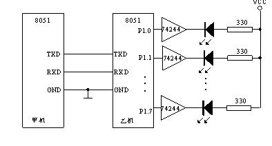
Machine A sends the program:
org 0000h
sta: mov tmod,#20h ; set the baud rate
mov tl1,#0FAh
mov th1,#0FAh
setb tr1
mov scon,#40h ; set working mode 1
clr ti
mov a,#00h
mov sbuf,a ; send the light signal
wait: jbc ti,cont ; clear the flag after sending successfully
ajmp wait ; wait for the sending to be completed
cont: sjmp sta ; repeat the sending
end
Machine B queries the working mode and receives:
org 0000h
mov tmod,#20h ; set the communication baud rate
mov tl1,#0FAh
mov th1,#0FAh
setb tr1
mov scon,#40h
clr ri
setb ren ;Allow receiving
wait: jbc ri,read ;Receiving successfully clear flag
ajmp wait ;Receiving is not finished waiting
read: mov a ,sbuf
mov p1,a ;Receive the light signal and send it to P1 port
sjmp $
end
Machine B receives in interrupt working mode
org 0000h
ajmp main
org 0023h
ajmp zd ;Switch to serial port interrupt program
START: MOV TMOD,#20h
mov tl1,#0FAh
mov th1,#0FAh
setb tr1
mov scon,#50h
clr ri
mov ie,#90h ;Open interrupt
MAIN:sjmp $ main program
zd: clr ri ;Clear receiving flag
; ===============The interrupt program needs to be improved ==============
mov a ,sbuf ;Read receiving signal
mov p1,a
MOV R1,A ; Send the received signal to the cache
reti ; Interrupt return
end

MOV PCON, #80H; SMOD=1
MOV R0, #50H; Set the first address of the data block
MOV R7, #20; Set the length of the data block
; =============================================================
WAIT: JBC RI, READ; After receiving a frame of data, RI is cleared and data is read in
AJMP WAIT; Not finished waiting
; ==============================================
READ: MOV A, SBUF; Read in data
JNB PSW.0, PZ; If the received number is an even number, transfer to
JNB RB8, ERR; If the received number is an odd number and the sending end is an even number, a communication error is made
SJMP RIGHT ; If they match, it is correct
PZ: JB RB8, ERR ; If the received number is an even number and the sending end is an odd number, it is an error
; ===========================================
RlGHT: MOV @R0, A ; Communication is correct, store data
INC R0 ; Change address pointer
DJNZ R7, WAIT ; Whether the data block is received, if not, continue
CLR PSW.5 ; Communication is correct, set F0 to 0
RET ; Return
ERROR: SETB PSW.5 ; Communication error, set F0 to 1
RET ; Return
Previous article:Listen to the technical experts talk about the 51 single chip microcomputer series
Next article:A Brief Discussion on the RETI Instruction of 51 Single Chip Microcomputer
 Professor at Beihang University, dedicated to promoting microcontrollers and embedded systems for over 20 years.
- Innolux's intelligent steer-by-wire solution makes cars smarter and safer
- 8051 MCU - Parity Check
- How to efficiently balance the sensitivity of tactile sensing interfaces
- What should I do if the servo motor shakes? What causes the servo motor to shake quickly?
- 【Brushless Motor】Analysis of three-phase BLDC motor and sharing of two popular development boards
- Midea Industrial Technology's subsidiaries Clou Electronics and Hekang New Energy jointly appeared at the Munich Battery Energy Storage Exhibition and Solar Energy Exhibition
- Guoxin Sichen | Application of ferroelectric memory PB85RS2MC in power battery management, with a capacity of 2M
- Analysis of common faults of frequency converter
- In a head-on competition with Qualcomm, what kind of cockpit products has Intel come up with?
- Dalian Rongke's all-vanadium liquid flow battery energy storage equipment industrialization project has entered the sprint stage before production
- Allegro MicroSystems Introduces Advanced Magnetic and Inductive Position Sensing Solutions at Electronica 2024
- Car key in the left hand, liveness detection radar in the right hand, UWB is imperative for cars!
- After a decade of rapid development, domestic CIS has entered the market
- Aegis Dagger Battery + Thor EM-i Super Hybrid, Geely New Energy has thrown out two "king bombs"
- A brief discussion on functional safety - fault, error, and failure
- In the smart car 2.0 cycle, these core industry chains are facing major opportunities!
- The United States and Japan are developing new batteries. CATL faces challenges? How should China's new energy battery industry respond?
- Murata launches high-precision 6-axis inertial sensor for automobiles
- Ford patents pre-charge alarm to help save costs and respond to emergencies
- New real-time microcontroller system from Texas Instruments enables smarter processing in automotive and industrial applications
- Download to get a gift | Collection of the best courseware: Tektronix Semiconductor Device Research Exchange and Keithley Test and Measurement Annual Seminar
- MSP430 Main Memory Bootloader Introduction
- I want to use POE to power some gadgets, but I don’t know what power chip to use?
- STM8L152 drives LCD experimental ultra-low power consumption code 7.2UA
- 5G and IoT will be the great equalizer
- 【XMC4800 Relax EtherCAT Kit Review】+ Getting started with DAVE and lighting up the LED
- R4 is clearly 130 ohms, but why is it 412.147M when simulated?
- Download the Power Path Protection course materials to make future designs more reliable
- EEWORLD University ---- Industrial Motor Driver - Introduction to Texas Instruments System Solutions
- Updated PYBCN_V2 and PYBNANO_V2 firmware

 Machine Vision Algorithms and Applications 2nd Edition


 京公网安备 11010802033920号