1 Introduction
In the information age, BP machines have become a common communication tool. At present, the transmitting equipment of my country's BP machine station is imported, with an output voltage of 13.8V and a current of 15-20A. The imported power supply does not have a thyristor part, and my country's power grid fluctuates greatly, so this low-cost voltage-stabilized power supply is designed. This design adds a thyristor phase control device to the series feedback adjustment type voltage-stabilized power supply, and uses the voltage drop across the adjustment tube to control the conduction angle of the thyristor trigger, maintaining the voltage drop of the adjustment tube unchanged, thereby designing a tracking high-power DC voltage-stabilized power supply. This voltage-stabilized power supply limits the power consumption of the adjustment tube and achieves high power.
The voltage-stabilized power supply is mainly composed of single-phase half-controlled bridge rectifier filter, linear voltage regulator and thyristor phase control, and is equipped with overcurrent protection, short circuit protection, overheat protection device and display part. When the voltage fluctuation of 220V grid is ±15%, the output voltage is 13.8V and the output current can reach 20A. Due to the use of thyristor phase control technology, the voltage drop at both ends of the adjustment tube can be limited to about 3V, the power consumption is not more than 40W, and the power efficiency is improved.
When the output current exceeds 20A, the current limiting protection can reduce the output current. If the output is short-circuited, the short-circuit protection outputs a blocking signal to turn off the thyristor. The fan is started when the adjustment tube temperature is higher than 60℃, the fan is turned off when the temperature is lower than 40℃, and the thyristor is turned off when the temperature is higher than 80℃. The power supply uses an integrated thyristor trigger, a dual operational amplifier and a voltage regulator with temperature compensation as the reference source, and is equipped with a three-terminal voltage regulator as an auxiliary power supply to achieve high precision.
2 Specific circuit implementation
The circuit structure block diagram is shown in Figure 1.
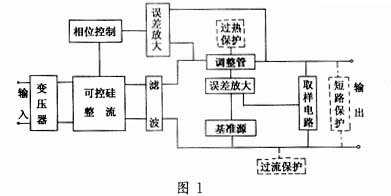
This circuit uses a unidirectional bridge half-controlled rectifier circuit to reduce costs. High-power or high-current regulated power supplies generally use L-C filter circuits. However, high-current filter reactors are large in size, heavy in weight, and expensive, so large capacitor filtering is still used in the design of this regulated power supply. The linear regulator part still uses the principle of series feedback adjustment regulator to form a closed-loop feedback system. It mainly includes: adjustment tube, sampling circuit, reference voltage source, and error comparison amplifier. Since the output current of the regulated power supply is 20A, the current is very large, so in order to reduce the power consumption of the adjustment tube, a parallel connection is adopted. In this power supply, the adjustment tube uses two high-power triodes in parallel, so that the current flowing through each tube is about 10A. In this way, the power consumption of each tube is not more than 40W, which reduces the power consumption of the adjustment tube. The collector current of the adjustment tube is about 10A, so a high-power crystal triode should be used, and β=40~50 should be selected. In this way, the base current should reach 2×0.3A, that is, 600mA. The output current of general integrated operational amplifiers is only tens of milliamperes, so the output end of the comparison amplifier circuit cannot directly drive the adjustment tube. Therefore, a driving stage is added between the output end of the comparison amplifier circuit and the base of the adjustment tube. Here, a low-power triode is selected to form a composite tube. The starting resistor Rc is 2k. The anti-vibration capacitor C is 10μF.
In the voltage stabilization circuit, the reference source is the reference for the entire voltage stabilization system, and the final effect of voltage stabilization depends on the level of the reference source. Therefore, in this power supply, the 2CW234 series silicon voltage regulator with temperature compensation characteristics is selected as the reference source, and its stable voltage is selected as 6.4V. It is powered by a three-terminal integrated voltage regulator with good characteristics, and the current limiting resistor uses a precision metal film resistor R (temperature coefficient is about ±1×10⁻⁵/℃). In order to reduce the influence of noise, the voltage regulator is encapsulated in a small container containing oil, and the noise index will be significantly improved.
The voltage sampling is shown in Figure 2. The collector-emitter voltage of the adjustment tube is divided by resistors, and the divided emitter voltage is sent to the inverting end of the comparison amplifier through a resistor; a voltage regulator is connected in series in the sampling circuit of the collector voltage, and the voltage drop of the adjustment tube is determined by the voltage regulator. Here, 3.3V is selected. The collector voltage is subtracted from the voltage regulator value and then divided and sent to the non-inverting end of the comparison amplifier. In order to ensure the sampling accuracy, the collector-emitter sampling resistors should be completely symmetrical, and precision metal film resistors of the same model with good temperature characteristics should be selected. The comparison amplifier uses an integrated operational amplifier and is connected in negative feedback.
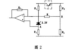
Let R1=R3, R2=R4; let the voltage division coefficient n=R2/(R1+R2); the output of the integrated operational amplifier is Uo; the amplification coefficient is K; the collector voltage of the adjustment tube is UC; the emitter voltage of the adjustment tube is UE; the voltage at point A is UA; the voltage at point B is UB; we have:

When the voltage drop of the adjustment tube increases, UcE rises, which increases Uo, that is, the control voltage Ub of the trigger increases, and the integrated trigger KJ785 is a negative type: the control voltage increases and the conduction angle decreases. Therefore, the trigger pulse moves back and the rectifier output decreases.
The thyristor rectifier is responsible for the first step of voltage stabilization, and the change of its output voltage is determined by the change of the conduction angle. The phase control part changes the conduction angle of the thyristor according to the change of the voltage drop of the adjustment tube, and then changes the output voltage of the rectifier filter circuit to maintain the voltage drop of the adjustment tube at about 3V. In this voltage-stabilized power supply, the KJ785 thyristor phase-shift trigger circuit is used. Because as a power supply product, it should strive to achieve the same function under the premise of good device performance, simple circuit and easy implementation. The trigger circuit can output two trigger pulses with a phase difference of 180 degrees, and can shift the phase in the range of 0 to 180 degrees. It can be used to control single-phase, bidirectional thyristors and transistors.
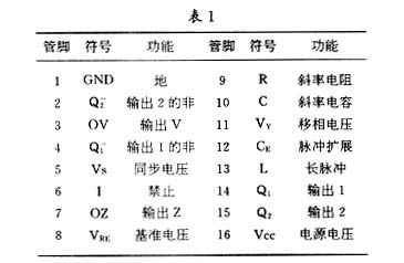
KJ785 consists of synchronous detection register circuit, reference power supply, sawtooth wave forming circuit, phase shift voltage and sawtooth wave comprehensive comparison circuit and logic control power amplifier. The sawtooth wave slope is determined by the external resistor at pin 9 and the external capacitor at pin 10. The pulse width is determined by the external capacitor at the pin. When the capacitor is not connected, the pulse width is determined by the internal capacitor, which is about 30μs.
KJ785 only needs a single power supply to work, and the trigger circuit is negative polarity, that is, the phase shift voltage increases and the conduction angle decreases. The synchronous voltage is input from pin 5, which can be directly taken from the grid voltage. The step-down current limiting resistor is the grid voltage × 103Ω, and the synchronous transformer can also be used to isolate the input. Pins 7 and 6 can provide control terminals for pulse trains and pulse blocking.
The functions of each pin are shown in Table 1.
Since the voltage stabilizer is a high-power power supply, it has transformers, rectifier diodes, thyristors, integrated voltage stabilizers, etc. that generate a lot of heat. More importantly, the adjustment tube is a high-power transistor that generates a lot of heat. Therefore, in this voltage stabilizer, a fan is used to supply air, and the cheap and high-performance thermistor AD590 is selected and installed on the heat sink of the adjustment tube. When the temperature reaches about 60°C, the fan is started to cool down, and when the temperature drops to about 40°C, the fan is turned off. When the temperature reaches 85°C, a blocking signal is sent to the thyristor trigger circuit to turn off the thyristor, and then turn off the circuit to prevent the adjustment tube from overheating and damage.
The circuit is shown in Figure 3.
External characteristics of AD590: At 0℃, the current is 273μA; for every 1℃ increase in temperature, the current increases by 1μA; for every 1℃ decrease in temperature, the current decreases by 1μA; the operating temperature is -50℃~+150℃; to avoid frequent or malfunction of the comparator, the hysteresis width is selected to be 1V.
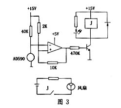

Take R = 40kΩ; select the integrated operational amplifier to be powered by a single power supply of +5V, which can be obtained by voltage division of CW78M15.
Assuming the comparator reference voltage is EmH at 65°C, we have:

Assume that the comparator reference voltage is EmL when the temperature is 40℃, then
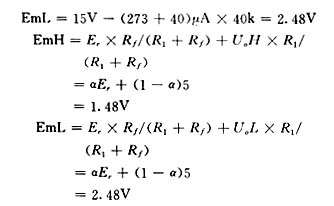
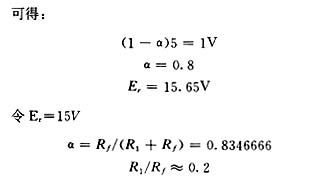
Take: R1=2k; Rf=10k
check:

Therefore: when the temperature is 61℃, start the fan; when it drops to 40℃, turn off the fan. When the temperature of the adjustment tube reaches about 80℃, the comparator outputs zero level, blocks the thyristor, and then shuts down the circuit.
In this voltage-stabilized power supply, the short-circuit protection function is to determine that a short circuit occurs when the output voltage is detected to be lower than 2V and a delay of 2s is passed. A blocking signal is sent to turn off the thyristor and the circuit to prevent damage to the device.
The function of current limiting protection is to reduce the base current of the adjustment tube and reduce the output current when the load current exceeds 20A.
3 Conclusion
This new tracking thyristor DC voltage regulator has low cost, good performance and high precision, and is suitable for use in BP transmitters. The output voltage range can reach 12V to 15V, and the current can reach 20A. The characteristic part of this power supply is phase control, which combines the advantages of thyristor and series feedback regulator, and overcomes the disadvantage of excessive power consumption of the adjustment tube in the traditional series feedback adjustment type voltage regulator.
Previous article:Design of multi-output auxiliary power supply based on half-bridge LLC resonant converter
Next article:Research on a new type of induction heating power supply dual parallel topology
- Popular Resources
- Popular amplifiers
-
 Hand-drawn revealing the basic principles and symbols of electronic circuits
 -
 Examples of methods and techniques for reading PLC ladder diagrams
 -
 Chip Manufacturing: A Practical Tutorial on Semiconductor Process Technology (Sixth Edition)
 -
 Electronic Engineers Must Read: Components and Technology (John M. Hughes)
- MathWorks and NXP Collaborate to Launch Model-Based Design Toolbox for Battery Management Systems
- STMicroelectronics' advanced galvanically isolated gate driver STGAP3S provides flexible protection for IGBTs and SiC MOSFETs
- New diaphragm-free solid-state lithium battery technology is launched: the distance between the positive and negative electrodes is less than 0.000001 meters
- [“Source” Observe the Autumn Series] Application and testing of the next generation of semiconductor gallium oxide device photodetectors
- 采用自主设计封装,绝缘电阻显著提高!ROHM开发出更高电压xEV系统的SiC肖特基势垒二极管
- Will GaN replace SiC? PI's disruptive 1700V InnoMux2 is here to demonstrate
- From Isolation to the Third and a Half Generation: Understanding Naxinwei's Gate Driver IC in One Article
- The appeal of 48 V technology: importance, benefits and key factors in system-level applications
- Important breakthrough in recycling of used lithium-ion batteries
- Innolux's intelligent steer-by-wire solution makes cars smarter and safer
- 8051 MCU - Parity Check
- How to efficiently balance the sensitivity of tactile sensing interfaces
- What should I do if the servo motor shakes? What causes the servo motor to shake quickly?
- 【Brushless Motor】Analysis of three-phase BLDC motor and sharing of two popular development boards
- Midea Industrial Technology's subsidiaries Clou Electronics and Hekang New Energy jointly appeared at the Munich Battery Energy Storage Exhibition and Solar Energy Exhibition
- Guoxin Sichen | Application of ferroelectric memory PB85RS2MC in power battery management, with a capacity of 2M
- Analysis of common faults of frequency converter
- In a head-on competition with Qualcomm, what kind of cockpit products has Intel come up with?
- Dalian Rongke's all-vanadium liquid flow battery energy storage equipment industrialization project has entered the sprint stage before production
- Allegro MicroSystems Introduces Advanced Magnetic and Inductive Position Sensing Solutions at Electronica 2024
- Car key in the left hand, liveness detection radar in the right hand, UWB is imperative for cars!
- After a decade of rapid development, domestic CIS has entered the market
- Aegis Dagger Battery + Thor EM-i Super Hybrid, Geely New Energy has thrown out two "king bombs"
- A brief discussion on functional safety - fault, error, and failure
- In the smart car 2.0 cycle, these core industry chains are facing major opportunities!
- The United States and Japan are developing new batteries. CATL faces challenges? How should China's new energy battery industry respond?
- Murata launches high-precision 6-axis inertial sensor for automobiles
- Ford patents pre-charge alarm to help save costs and respond to emergencies
- New real-time microcontroller system from Texas Instruments enables smarter processing in automotive and industrial applications
- CC1101 Study Notes - Preliminary Understanding
- 5G commercial use is on the way, are you ready?
- Chat with Vicor engineers about efficient power supply and learn about modular power solutions for drones!
- Download the practical guide - Motor Control Basics
- DDR4 signal reference power layer, will the impedance have any impact?
- Questions about adjustable color temperature LED lamp circuit
- Oscilloscope test of auto repair model CAN line test
- How to Accurately Test Phase Noise
- [NXP Rapid IoT Review] Power on (finally received the goods)
- [XMC4800 Relax EtherCAT Kit Review] + Getting Started with DAVE, XMC4800 EtherCAT Slave Module Example Analysis

 Hand-drawn revealing the basic principles and symbols of electronic circuits


 京公网安备 11010802033920号