The MAX6954 is a universal display driver capable of controlling multiple discrete, 7-segment, 14-segment, or 16-segment LED displays through a single serial port. This application note introduces typical applications and configurations for driving 8-bit monochrome, 7-segment LED displays. For detailed information about the MAX6954, please refer to the MAX6954 data sheet.
The application notes "Using the MAX6954 to Drive a 16-Segment LED Display" and "Using the MAX6954 to Drive a 14-Segment LED Display" are similar to this article and describe how to configure the MAX6954 to drive a 16-segment and 14-segment display respectively. ?
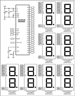
Figure 1. MAX6954 driving 7-segment display circuit.
A common application for the MAX6954 is to drive up to 16 bits of 7-segment monochrome LEDs. This application note guides users on how to connect the MAX6954 to a 7-segment display, and how to configure its internal registers to control the display of hexadecimal characters.
The MAX6954 uses a multiplexing technique that alternates the polarity of the driver ports to reduce pin count. This is different from standard LED multiplexing connections where the driver's cathode and anode pins are used separately. The application note "Charlieplexing - Reduced Pin-Count LED Display Multiplexing" discusses this technology. Table 1 is the connection table between the MAX6954 and the 7-segment display. This table is compatible with the multiplexing configuration of the MAX6954 and its built-in font for hexadecimal characters. The letters in Table 1 correspond to the segment identifiers in Figure 2. Figure 1 is a schematic circuit diagram of the MAX6954 driving a sixteen-bit 7-segment display.
Table 1. Connection table with 16-bit 7-segment display
After completing the connection between the MAX6954 and the 7-segment display, you can use the display test mode to check the correctness of the connection. The display test mode is not affected by the control and data registers. It lights up all segments of the display but does not change the contents of any register. Writing 0x01 to Register 0x07 enables display test mode. If there are unlit segments on the display in test mode, it means the connection is incorrect. Write 0x00 to register 0x07 to exit display test mode.

Figure 2. Segment identification of a 7-segment display.
After completing the wiring check, the MAX6954 register values need to be set according to the requirements for driving a 7-segment display. Table 2 includes the initial power-on values of some important registers of the MAX6954. When the MAX6954 is first powered on, it is in shutdown mode, all displays are blanked, the 7-segment font mode is selected and the number of scanned digits is set to the maximum, which is eight digits. The MAX6954 can be set to drive a 7-segment display by writing 0xFF to Register 0x0C. The default value of the decoding mode register (0x01) is suitable for a 7-segment display.
Table 2. MAX6954 register initial power-on state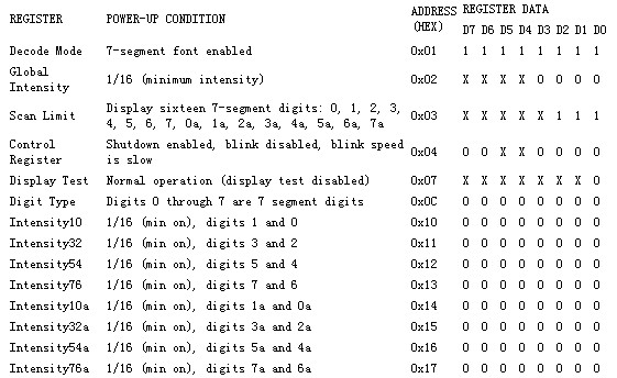

The S bit is used to select shutdown mode or normal operating mode (read/write).
Bit B is used to select the blink rate (read/write).
The E bit is used to globally enable or disable the flashing function (read/write).
The T bit is used to reset the flash sequence (this data is not stored - transient bit).
The R bit is used to globally clear the P0 and P1 two-level registers corresponding to all display bits (this data is not stored - transient bit).
The I bit is used to select whether to control the brightness of each bit globally or individually (read/write).
The P bit returns the current blink timing phase (read-only—writing a value to this bit will be ignored).
Table 3. Configuration register format CONFIGURATION 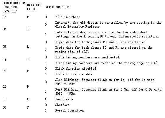
Start the display driver by writing 0x01 to register 0x04, and at the same time set the working mode to global brightness control and disable flickering. The internal oscillator starts when the MAX6954 exits shutdown mode, and the oscillator output pin is OSC_OUT. Note that when the power-on status of data control registers 0x60 to 0x67 is 0x20 or no segments are lit, the 7-segment display remains blank (see Table 2 and Figure 3).
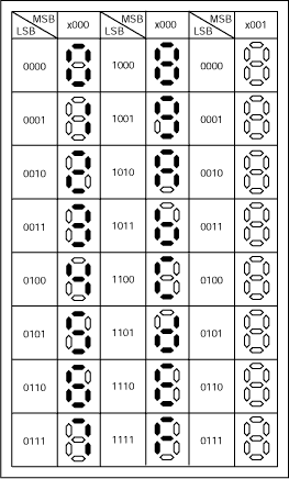
Figure 3. 7-segment display font
MAX6954 has a built-in hexadecimal font for 7-segment display, using 7 bits to represent hexadecimal characters, and the 8th bit is used to select whether to light the decimal point (DP) (see Table 4) . The data register has two levels, P0 and P1. Each display bit is represented by 2 bytes in memory, one byte is located in P0 and the other is located in P1 (see Table 7). The data register is a mapped address, so each bit of data can be updated in P0 (register 0x20 to 0x2F), or in P1 (register 0x20 to 0x4 F), or both levels can be updated simultaneously (register 0x60 to 0x67). The data in the data register does not directly control the display of each segment in the 7-segment display. Instead, it is used to address the character generator that stores 7-segment word pattern data (see Figure 3). The lower 7 bits of register data (D6 to D0) are used to select characters from the font. The highest bit (D7) controls the decimal point (DP) display; setting it to 1 will display DP, and setting it to 0 will not display DP.
Table 4. Numeric type data register format

If the flash function is disabled by the flash enable bit E of the configuration register (see Table 3), the data in the data register in P0 is used for display multiplexing. The data in the data register in P1 is not used. If the blink function is enabled, the data multiplexing displays in P0 and P1 are used alternately. The data in P0 and P1 are respectively applied to different phases of the alternating changes of the flashing clock, thereby multiplexing the LED display to achieve the flashing function.
The following is an example of using the MAX6954 driver to display the Maxim/Dallas Sales Department phone number: 1 800 629 4642. Set the configuration register to disable the flash function, so that data bits 0 to 7 can be controlled respectively by writing data to registers 0x20 to 0x2F. Use the font pattern in Figure 3 to get the code corresponding to each character.
Table 5. Telephone 800.629.4642 Example
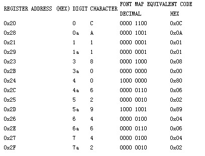
Adjust the display brightness by writing data to register 0x02 (global brightness control register). The brightness can be adjusted between 0x00 (minimum brightness, 1/16 current) and 0xFF (maximum brightness, 15/16 current). The brightness of each bit can also be controlled individually. Refer to the MAX6954 data sheet for details on display brightness adjustment and other advanced features such as GPIO and key scanning.
Table 6. Routine command set REGISTER

Table 7. Partial register address map of MAX6954/MAX6955?

?
Previous article:Generate consistent LED brightness in RGB displays
Next article:Using MAX6954 to drive a 14-segment LED display
- Popular Resources
- Popular amplifiers
- MathWorks and NXP Collaborate to Launch Model-Based Design Toolbox for Battery Management Systems
- STMicroelectronics' advanced galvanically isolated gate driver STGAP3S provides flexible protection for IGBTs and SiC MOSFETs
- New diaphragm-free solid-state lithium battery technology is launched: the distance between the positive and negative electrodes is less than 0.000001 meters
- [“Source” Observe the Autumn Series] Application and testing of the next generation of semiconductor gallium oxide device photodetectors
- 采用自主设计封装,绝缘电阻显著提高!ROHM开发出更高电压xEV系统的SiC肖特基势垒二极管
- Will GaN replace SiC? PI's disruptive 1700V InnoMux2 is here to demonstrate
- From Isolation to the Third and a Half Generation: Understanding Naxinwei's Gate Driver IC in One Article
- The appeal of 48 V technology: importance, benefits and key factors in system-level applications
- Important breakthrough in recycling of used lithium-ion batteries
- Innolux's intelligent steer-by-wire solution makes cars smarter and safer
- 8051 MCU - Parity Check
- How to efficiently balance the sensitivity of tactile sensing interfaces
- What should I do if the servo motor shakes? What causes the servo motor to shake quickly?
- 【Brushless Motor】Analysis of three-phase BLDC motor and sharing of two popular development boards
- Midea Industrial Technology's subsidiaries Clou Electronics and Hekang New Energy jointly appeared at the Munich Battery Energy Storage Exhibition and Solar Energy Exhibition
- Guoxin Sichen | Application of ferroelectric memory PB85RS2MC in power battery management, with a capacity of 2M
- Analysis of common faults of frequency converter
- In a head-on competition with Qualcomm, what kind of cockpit products has Intel come up with?
- Dalian Rongke's all-vanadium liquid flow battery energy storage equipment industrialization project has entered the sprint stage before production
- Allegro MicroSystems Introduces Advanced Magnetic and Inductive Position Sensing Solutions at Electronica 2024
- Car key in the left hand, liveness detection radar in the right hand, UWB is imperative for cars!
- After a decade of rapid development, domestic CIS has entered the market
- Aegis Dagger Battery + Thor EM-i Super Hybrid, Geely New Energy has thrown out two "king bombs"
- A brief discussion on functional safety - fault, error, and failure
- In the smart car 2.0 cycle, these core industry chains are facing major opportunities!
- The United States and Japan are developing new batteries. CATL faces challenges? How should China's new energy battery industry respond?
- Murata launches high-precision 6-axis inertial sensor for automobiles
- Ford patents pre-charge alarm to help save costs and respond to emergencies
- New real-time microcontroller system from Texas Instruments enables smarter processing in automotive and industrial applications
- STM32 output 4-20MA or 0-10V circuit sharing
- LIS2MDL array PCB engineering and code information for magnetic nail navigation AGV car
- Live Review: Rochester Electronics Semiconductor Full-Cycle Solutions (including videos, materials, Q&A)
- How to understand this parameter in the MOS tube specification?
- Why is it necessary to use a four-pin Kelvin connected resistor for current detection?
- Purgatory Legend-12864 LCD War
- Live Review: How to Design High-Performance Servo Drives Using Infineon IGBT7
- [Raspberry Pi 4B Review] + ARIA2 Remote Download Server Construction
- Italian court upholds enforceability of open source software license
- New support for C++ code in STM32 and examples of user C modules written in C++ in MicroPython

 Virtualization Technology Practice Guide - High-efficiency and low-cost solutions for small and medium-sized enterprises (Wang Chunhai)
 Digilent Vivado library
 Arduino DUE drives Adafruit Sharp Memory Display Breakout screen


 京公网安备 11010802033920号