1 Introduction
Generally, the main circuit structure of the servo system is shown in Figure 1. Energy is transmitted from the power grid to the motor through rectifiers, filters, inverters, etc. When the motor works in the power generation state, that is, when the motor brakes quickly or carries a potential load, the energy transmission needs to be reversed. The energy will accumulate on the filter capacitor, generating a pump voltage. If the pump voltage is too high, it will threaten the system. Safety. The simplest method to control the pump voltage is: after the pump voltage is generated, connect an energy-consuming resistor between the DC buses to release the energy. If the motor brakes frequently or operates with a potential load for a long time, energy will be wasted seriously; at the same time, the ambient temperature will increase due to heating of the resistor, which will affect the reliability of the system. The circuit designed in this article can solve this problem well.
2 Overview of system working principle
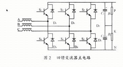
Replace the three-phase uncontrolled rectifier in Figure 1 with a controlled converter, and connect three high-frequency choke reactors in series to the three-phase power input end to suppress possible bidirectional (power grid, servo system) electromagnetic interference, and when the converter works in the inverter state, it plays the role of an equivalent DC reactor, as shown in Figure 2.
  |
When the motor is working in the electric state, the high-power switching devices S1 to S6 of the controllable converter are all in the off state, and the six freewheeling diodes form a three-phase uncontrolled bridge rectifier. The working condition is the same as Figure 1.
When the motor works in the power generation state, the inverter works in the rectification state, and the controllable converter works in the inversion state, making the motor work in the regenerative braking state. At this time, the filter capacitor stores energy and the DC bus voltage rises. After exceeding the power grid voltage value, the diodes D1~D6 are reversely blocked; when the DC bus voltage continues to rise and exceeds the set upper limit allowable value UdH, the converter The inverter starts working and inverts the energy on the DC bus back to the grid. At this time, the high-frequency choke reactor will balance the difference between the DC bus voltage and the grid line voltage to ensure the normal operation of the inverter state. When the DC bus voltage drops back to the lower limit set value UdL, the converter is turned off. Issues to consider regarding energy feedback include:
1) The feedback current must meet the requirements of the feedback power and cannot be greater than the maximum current allowed by the inverter;
2) Only when the DC bus voltage is higher than the set value, the inverter can be started for energy feedback;
3) In order to increase the feedback power, try to perform feedback when the grid voltage is high, because if the feedback current is constant, the higher the grid voltage, the greater the feedback power.
Therefore, the system must have a voltage control circuit, a synchronous control circuit and a current limiting circuit. The control of current and voltage is completed by two hysteresis comparators, and the synchronous control is completed by the synchronous detection and control circuit.
3 Control circuit design
3.1 Design of voltage detection and control circuit
The purpose of designing the voltage control circuit is: when the motor is working in the power generation state and the DC bus voltage Ud rises to exceed the set value UdH, the switching tube in the converter is started to invert the energy on the DC bus and feedback it back. The power grid forces Ud to fall back; when Ud is less than another set value UdL, the switch tube is turned off. In order to avoid the inverter starting and shutting down too frequently, the voltage control is hysteresis control mode UdL
 |
In the formula: U is the effective value of the phase voltage.
Under normal circumstances, when the grid phase voltage is 220V, UdL=630V can be set, the loop width of the voltage hysteresis control is 20V, UdH=650V, the linear photoelectric isolator NEC200 is used to detect the DC bus voltage, and the DC bus voltage is linearly Converted into a weak voltage signal, used as the inverting input of the voltage hysteresis controller. The voltage detection and control circuit is shown in Figure 3. Uv is one of the conditions for controlling the main switch of the feedback inverter.
 |
3.2 Current detection and generation of current control signals
Since the current on the DC bus is equal to the current through the converter switch and the line current fed back to the grid, it is only necessary to install a LEM current sensor on the DC bus connected to the converter to detect the energy feedback process. All line current IL. When IL is lower than the hysteresis lower limit ILL, UI is high level, allowing the inverter switch to be turned on; when IL is higher than the hysteresis upper limit ILH, UI is low level, and the converter switch is turned off. After shutdown, under the effect of freewheeling of the choke reactor, the current direction of the energy feedback line remains unchanged, the corresponding diode in the converter freewheels, and the current on the DC bus is reversed. Therefore, it is necessary to rectify the voltage signal output by the LEM to obtain the line current feedback signal Iv of the energy feedback. Iv is used as the second condition for controlling the on and off of the main switch of the feedback inverter. The current detection and current control circuit is composed of a current sensor circuit, a precision rectifier circuit and a hysteresis comparator, as shown in Figure 4.
 |
3.3 Phase synchronization control circuit
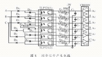
When the converter is working in the inverter state, in order to obtain greater energy feedback, when the feedback line current is constant, energy feedback should be carried out in the high voltage section of the power grid as much as possible. Therefore, the switching state of each power switching device of the converter and the phase of the grid voltage should meet the synchronization relationship as shown in Figure 6. For this purpose, the synchronous control circuit shown in Figure 5 is designed. In Figure 5, ug1 to ug6 are the conduction permission synchronous control signals of the power switching devices S1 to S6 respectively. Connect A, B, and C in Figure 2 and Figure 5 together, and connect the system to the power grid, regardless of phase sequence. No matter how it changes, the synchronization relationship shown in Figure 6 remains unchanged. Under this synchronization relationship, the ideal phase voltage and phase current waveforms are shown in Figure 7. Let u1~u6 be the drive control signals of S1~S6 respectively, with high level on and low level off. The drive control signals u1~u6 can be controlled by protection signal, voltage control signal Uv, current control signal Iv and synchronization control respectively. The signal UTi is obtained after the AND.
 |
 |
4 Application example analysis
When applied in a DSP-controlled synchronous motor servo system, the energy feedback power P=6.5kW, the phase voltage U=220V, the maximum switching frequency of the converter fmax=10kHz, the maximum allowable current is 25A, and ILH is set to 20A. ,ILL=10A, UdL=630V, UdH=650V.
4.1 Calculation of choke reactor
The choke reactor plays an important role in this pump voltage control circuit. There are three main requirements for it, namely inductance, operating frequency and operating current. The requirements for inductance depend on the set value of the feedback current and the rated switching frequency of the converter. Assume that during the energy feedback process, the forward voltage the reactor withstands is:
Under the action of , the time for the feedback current to rise from ILL to ILH is ton. The inductance value of each reactor is L. When IL=ILH, the converter switching device is turned off, then
 |
It can be seen that after the inductance of the reactor is determined in UdH, ILH, ILL, and L, the smaller UdL is, the higher the switching frequency of the converter power switch is. When UdL is the smallest and the switching frequency is the largest, the required inductance is the smallest. At this time, UdL=
 |
4.2 Estimation of feedback power P
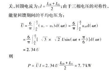
When the grid voltage is constant, the feedback power is related to the feedback current, and the feedback current is:
 |
Meets the requirement of 6.5kW feedback.
5 Conclusion
The voltage and current waveforms captured by the oscilloscope during braking of the above synchronous motor servo system are shown in Figure 8, which is consistent with the theoretical analysis and meets the design requirements. The application in the above system shows that this method is feasible and has certain practical value.
Previous article:Vector frequency conversion speed regulating power supply for bridge crane
Next article:Design of battery charger using mixed-signal approach
Recommended ReadingLatest update time:2024-11-16 23:48


- Popular Resources
- Popular amplifiers
-
 Microgrid Stability Analysis and Control Microgrid Modeling Stability Analysis and Control to Improve Power Distribution and Power Flow Control (
 -
 Modern Electronic Technology Training Course (Edited by Yao Youfeng)
 -
 New Energy Vehicle Control System Inspection and Maintenance (Edited by Bao Pili)
 -
 Intelligent Control Technology of Permanent Magnet Synchronous Motor (Written by Wang Jun)
- MathWorks and NXP Collaborate to Launch Model-Based Design Toolbox for Battery Management Systems
- STMicroelectronics' advanced galvanically isolated gate driver STGAP3S provides flexible protection for IGBTs and SiC MOSFETs
- New diaphragm-free solid-state lithium battery technology is launched: the distance between the positive and negative electrodes is less than 0.000001 meters
- [“Source” Observe the Autumn Series] Application and testing of the next generation of semiconductor gallium oxide device photodetectors
- 采用自主设计封装,绝缘电阻显著提高!ROHM开发出更高电压xEV系统的SiC肖特基势垒二极管
- Will GaN replace SiC? PI's disruptive 1700V InnoMux2 is here to demonstrate
- From Isolation to the Third and a Half Generation: Understanding Naxinwei's Gate Driver IC in One Article
- The appeal of 48 V technology: importance, benefits and key factors in system-level applications
- Important breakthrough in recycling of used lithium-ion batteries
- Innolux's intelligent steer-by-wire solution makes cars smarter and safer
- 8051 MCU - Parity Check
- How to efficiently balance the sensitivity of tactile sensing interfaces
- What should I do if the servo motor shakes? What causes the servo motor to shake quickly?
- 【Brushless Motor】Analysis of three-phase BLDC motor and sharing of two popular development boards
- Midea Industrial Technology's subsidiaries Clou Electronics and Hekang New Energy jointly appeared at the Munich Battery Energy Storage Exhibition and Solar Energy Exhibition
- Guoxin Sichen | Application of ferroelectric memory PB85RS2MC in power battery management, with a capacity of 2M
- Analysis of common faults of frequency converter
- In a head-on competition with Qualcomm, what kind of cockpit products has Intel come up with?
- Dalian Rongke's all-vanadium liquid flow battery energy storage equipment industrialization project has entered the sprint stage before production
- Allegro MicroSystems Introduces Advanced Magnetic and Inductive Position Sensing Solutions at Electronica 2024
- Car key in the left hand, liveness detection radar in the right hand, UWB is imperative for cars!
- After a decade of rapid development, domestic CIS has entered the market
- Aegis Dagger Battery + Thor EM-i Super Hybrid, Geely New Energy has thrown out two "king bombs"
- A brief discussion on functional safety - fault, error, and failure
- In the smart car 2.0 cycle, these core industry chains are facing major opportunities!
- The United States and Japan are developing new batteries. CATL faces challenges? How should China's new energy battery industry respond?
- Murata launches high-precision 6-axis inertial sensor for automobiles
- Ford patents pre-charge alarm to help save costs and respond to emergencies
- New real-time microcontroller system from Texas Instruments enables smarter processing in automotive and industrial applications
- FPGA introductory series experimental tutorial——
- 【DIY Creative LED】The soldered board has normal charging function
- ESP32 SD/MMC hardware connection method
- Domestic chips are amazing. I just applied for a board. CH579 is so small but it integrates network, USB, and Bluetooth.
- Gallium nitride substrate production technology and equipment
- Safety temperature standards for main components of switching power supplies
- Auxiliary trainer for plank and push-up exercises
- MicroPython will add serial port interrupt function
- MOS tube
- C6678 on-chip storage space allocation mechanism

 Microgrid Stability Analysis and Control Microgrid Modeling Stability Analysis and Control to Improve Power Distribution and Power Flow Control (


 京公网安备 11010802033920号