1 Introduction
Keywords:AT89S51
Reference address:Design and implementation of digital controlled DC voltage regulated power supply based on single chip microcomputer
DC regulated power supply is one of the commonly used equipment in electronic technology, and is widely used in teaching, scientific research and other fields. The traditional multifunctional DC regulated power supply has simple functions, is difficult to control, has low reliability, large interference, low precision, large size and high complexity. There are many types of ordinary DC regulated power supplies. However, they all have the following problems: the output voltage is adjusted by coarse adjustment (band switch) and fine adjustment (potentiometer). In this way, when the output voltage needs to be accurately output or needs to be changed within a small range (such as 1.02~1.03V), the difficulty is greater. In addition, with the increase of usage time, the band switch and potentiometer will inevitably have poor contact, which will affect the output. Overload is often protected by hardware with current limiting or current cutoff type, the circuit structure is complex, and the voltage stabilization accuracy is not high. This paper designs an intelligent high-precision simple DC power supply with a single-chip microcomputer as the core, which overcomes the shortcomings of traditional DC voltage sources and has high application value.
2 System Hardware Design
2.1 Overall system structure
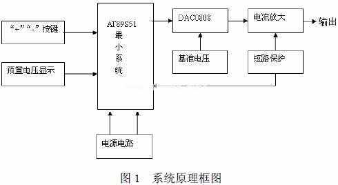
This system is a digitally controlled DC power supply with AT89S51 single-chip microcomputer as the core controller. It has voltage preset, step adjustment, output voltage signal and preset voltage signal that can be displayed simultaneously. Its hardware principle block diagram is shown in Figure 1. The system consists of eight parts: AT889S51 control circuit, keyboard circuit, power supply circuit, D/A circuit, power amplifier circuit, short circuit protection and alarm circuit, voltage stabilization output circuit, and LED display circuit. The system controls the rise and fall of the preset voltage through the three buttons of "switch", "+", and "-", and displays it through the digital tube. The AT89S51 single-chip microcomputer sends out the corresponding digital signal, outputs the current after D/A conversion, and finally stabilizes after conversion by the integrated operational amplifier LM358, transistor amplification, and RC network filtering. At the same time, the output voltage is displayed by the LED digital tube; the measured value is measured by the digital voltmeter.

2.2 CNC part
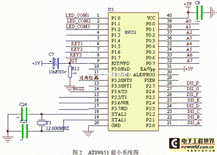
It is mainly controlled by the AT89S51 minimum system, which has to complete the functions of keyboard control, preset voltage display control, short circuit protection control and alarm control, etc. The AT89S51 minimum system is shown in Figure 2.

2.2.1 Keyboard interface circuit
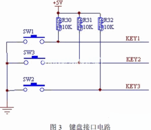
The keyboard interface circuit is shown in Figure 3. The keyboard design is controlled by three buttons: the "switch" key, the "+" key, and the "-" key, and three external pull-up resistors are connected to control the keyboard debounce. These three buttons are respectively connected to the P1.0, P1.1, and P1.2 interfaces of the microcontroller for control.

2.2.2 Preset voltage display circuit
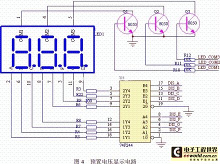
The preset voltage display circuit is shown in Figure 4. This design uses the decoder driver 74F244 to drive the LED digital tube to display the preset voltage, which is controlled by the microcontroller P2.0~P2.7 interface. The LED common cathode control end is controlled by the P1.4~P1.6 interface, and the triode 8050 is used to control the LED display.

2.3 Power supply
2.3.1 Main power circuit
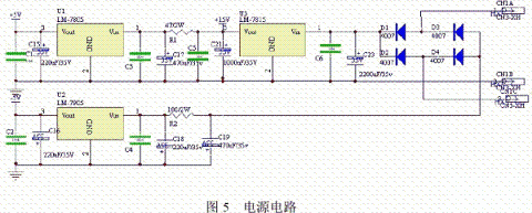
The power supply part inputs 220V, 50Hz AC power and outputs three voltages required by the whole machine: +5V, +15V, -5V, which are mainly used for the numerical control part and D/A conversion chip; +15V is used as the positive power supply of the op amp and also the main power supply of the voltage-stabilized output circuit. The power module part expands the -5V negative voltage and also serves as the negative power supply of the op amp, as shown in Figure 5.

2.3.2 Voltage Regulated Output Section
The voltage stabilization output part converts the voltage control word data sent by the control part into a stable voltage output. It consists of a converter (DAC0808), an integrated operational amplifier LM358, a transistor, a reference voltage source (+15V), and an overcurrent detection circuit. The voltage stabilization output module includes an overcurrent detection circuit. When the power supply is overcurrent, the overcurrent detection circuit outputs a low level and sends it to the INT0 of the CPU to apply for an interrupt. After the CPU receives it, it delays 5ms.
3 System Software Design
The software control program consists of two parts: the main program and the overcurrent protection program, which mainly realizes functions such as step addition and subtraction, D/A conversion, keyboard scanning, LED display, and current alarm.
3.1 Main Program
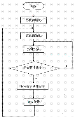
First, initialize the system, that is, initialize the AT89S51 single-chip microcomputer system, then set the system time, call the key processing subroutine to determine whether a key is pressed, if so, call the display processing program, the display processing program displays the preset voltage on the digital tube, the signal controlled by the single-chip microcomputer is converted by D/A, and then judged by the detection circuit whether it is short-circuited, if short-circuited, the interrupt protection is started. Otherwise, the voltage stabilization output is achieved. The main flow chart is shown in Figure 6.

Figure 6 Main program flow chart
3.2 Overcurrent protection procedure
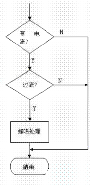
The signal converted from the digital-to-analog conversion circuit passes through the current detection circuit and sends the detected signal to the single-chip microcomputer minimum system for processing. If there is overcurrent, the buzzer will sound. The overcurrent protection program flow chart is shown in Figure 7.

Figure 7 Overcurrent protection program flow chart
4 Conclusion
This design uses a single-chip microcomputer as the core to design an intelligent voltage-stabilized power supply. It is not only simple in circuit, compact in structure, low in price, but also has excellent performance. The developed intelligent voltage-stabilized power supply can use the single-chip microcomputer to set up a thorough protection monitoring system to ensure reliable operation of the power supply. The output voltage is displayed digitally and input is input by keyboard. The power supply has a beautiful appearance, is easy to operate and use, and has a high use value.
Previous article:Design of Microampere-level Digital Control Constant Current Source
Next article:Precise control of power supply voltage in embedded systems
Recommended ReadingLatest update time:2024-11-16 22:24
Principle and design of adjustable regulated power supply based on AT89S51 control

The regulated power supply introduced in this article is controlled by AT89S51 microcontroller. Use the potentiometer as the memory component, the 555 circuit as the A/D conversion, and the discrete components as the D/A conversion. It is easy to use and the whole machine cost is low. 1. Working principle The circui
[Microcontroller]

How to use AT89S51 microcontroller to realize the design of home voice alarm system

introduction The modern living pattern makes the safety of family life particularly important. Currently, security prevention and alarm systems are important guarantees for ensuring the safety of homes and residents. The best way to prevent theft is to issue a voice warning when criminals attempt to invade, increasing
[Microcontroller]

Using these 6 methods, CNC workshops can achieve cost reduction and efficiency improvement
Amid growing competition, the CNC (computerized numerical control) manufacturing industry is locked in a constant battle to contain production costs, improve product quality, and meet customer demands. To meet these challenges, CNC shops are adopting state-of-the-art technology to reduce costs and increase productiv
[robot]
- Popular Resources
- Popular amplifiers
Recommended Content
Latest Power Management Articles
- MathWorks and NXP Collaborate to Launch Model-Based Design Toolbox for Battery Management Systems
- STMicroelectronics' advanced galvanically isolated gate driver STGAP3S provides flexible protection for IGBTs and SiC MOSFETs
- New diaphragm-free solid-state lithium battery technology is launched: the distance between the positive and negative electrodes is less than 0.000001 meters
- [“Source” Observe the Autumn Series] Application and testing of the next generation of semiconductor gallium oxide device photodetectors
- 采用自主设计封装,绝缘电阻显著提高!ROHM开发出更高电压xEV系统的SiC肖特基势垒二极管
- Will GaN replace SiC? PI's disruptive 1700V InnoMux2 is here to demonstrate
- From Isolation to the Third and a Half Generation: Understanding Naxinwei's Gate Driver IC in One Article
- The appeal of 48 V technology: importance, benefits and key factors in system-level applications
- Important breakthrough in recycling of used lithium-ion batteries
MoreSelected Circuit Diagrams
MorePopular Articles
- Innolux's intelligent steer-by-wire solution makes cars smarter and safer
- 8051 MCU - Parity Check
- How to efficiently balance the sensitivity of tactile sensing interfaces
- What should I do if the servo motor shakes? What causes the servo motor to shake quickly?
- 【Brushless Motor】Analysis of three-phase BLDC motor and sharing of two popular development boards
- Midea Industrial Technology's subsidiaries Clou Electronics and Hekang New Energy jointly appeared at the Munich Battery Energy Storage Exhibition and Solar Energy Exhibition
- Guoxin Sichen | Application of ferroelectric memory PB85RS2MC in power battery management, with a capacity of 2M
- Analysis of common faults of frequency converter
- In a head-on competition with Qualcomm, what kind of cockpit products has Intel come up with?
- Dalian Rongke's all-vanadium liquid flow battery energy storage equipment industrialization project has entered the sprint stage before production
MoreDaily News
- Allegro MicroSystems Introduces Advanced Magnetic and Inductive Position Sensing Solutions at Electronica 2024
- Car key in the left hand, liveness detection radar in the right hand, UWB is imperative for cars!
- After a decade of rapid development, domestic CIS has entered the market
- Aegis Dagger Battery + Thor EM-i Super Hybrid, Geely New Energy has thrown out two "king bombs"
- A brief discussion on functional safety - fault, error, and failure
- In the smart car 2.0 cycle, these core industry chains are facing major opportunities!
- The United States and Japan are developing new batteries. CATL faces challenges? How should China's new energy battery industry respond?
- Murata launches high-precision 6-axis inertial sensor for automobiles
- Ford patents pre-charge alarm to help save costs and respond to emergencies
- New real-time microcontroller system from Texas Instruments enables smarter processing in automotive and industrial applications
Guess you like
- What is the principle behind this?
- Sell yourself, sell yourself
- ICE40LP1K CDONE pin is always low
- Is there a company where you can have breakfast until 10 o'clock, take a nap until 2 o'clock, and receive 18 months' salary per year?
- [Automatic clock-in and walking timing system based on face recognition] Maixbit/MaixPy pitfall! The audio playback function blocks the call
- 1
- Wireless Earbud Battery Ultra-Low Standby Power Consumption Reference Design
- Fake news and exaggerated hype are hurting China's IC industry. Silence is not the solution (Reprinted)
- TA0CCR0 interrupt of msp430
- What are the 9 most important applications of the Internet of Things (IoT)?

 西门子S7-12001500 PLC SCL语言编程从入门到精通 (北岛李工)


 京公网安备 11010802033920号