In order to ensure that the measurement results have a certain statistical credibility, it is necessary to wait for about 10 failures. As mentioned above, the failure rate is exponentially related to Vds, and the typical application voltage is usually lower than V(BR)DSS. For example, for a 650V CoolMOS at a 520V bus voltage, assuming 10FIT/device, it means that it takes 10 years for 1 failure to occur in 1000 devices. In order to shorten the test time and have sufficient failure statistics under actual working voltage conditions, a high-energy proton or neutron beam acceleration test based on JEP151 has been established, with an acceleration factor of up to 10 9. This allows a single round of testing to be completed in half an hour, and corresponding series tests of different combinations are also faster.
The energy spectrum of the artificial radiation source used in the accelerated test is limited or has only one type of particle. Therefore, Infineon uses two methods based on JEP152, storage test and accelerated test, to ensure data consistency.
3. Establishment of the OBC general mission profile model
An accurate mission profile is essential to evaluate the robustness of high voltage semiconductors in harsh automotive application environments. The following describes a generic mission profile model for an OBC/HV-LV DC-DC converter based on actual applications and setting certain conditions.
1. Working status
When the vehicle is in motion, most of the onboard power electronic equipment is in active operation, including HV-LV DC-DC. However, the OBC is in the opposite state and only works when the car is parked, AC power is available, and the BMS system allows charging. Of course, in the reverse application scenarios of V2L, V2G or V2V, the battery will also provide energy to devices outside the vehicle.
Table 1 shows the three most important operating modes of electric vehicles and defines the operating states of HV-LV DC-DC and OBC.

2. Working hours
Based on the above table, Infineon has created an operating time model based on experience to evaluate the failure rate of power semiconductors in OBC and HV-LV DC-DC systems based on a 15-year vehicle usage period. As shown in Table 2:

3. Temperature model
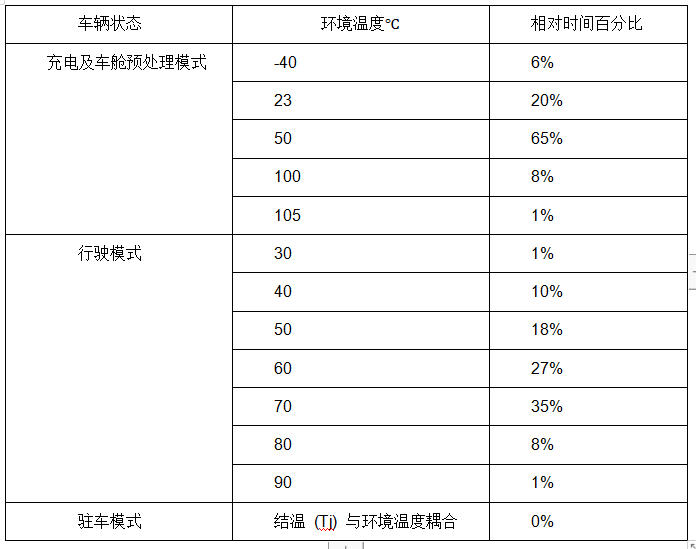
Another important factor in calculating the FIT rate is the junction temperature of the high-voltage power semiconductor, which is coupled with the water cooling system in the vehicle. Table 3 shows the temperature model of the vehicle state:

4. Altitude model
As mentioned above, an important accelerating factor of cosmic radiation-induced failures is altitude. Infineon has created an altitude model based on the altitude distribution of the global population, as shown in Table 4:

5. System Model
The more accurate the electrical and environmental conditions are, the more accurate the FIT results will be. For OBC and HV-LV DC-DC, we only consider high-voltage devices because cosmic radiation has a more serious impact on high-voltage devices. As shown in the dashed box in Figure 6:

Figure 6: High voltage device location
DC-link bus voltage model:
The bus voltage dominates the PFC and DCDC primary side. Accurately modeling the long-term bus voltage is critical. To set the normal bus voltage:
Vstess1.nor=400V
In addition, assuming that the voltage under overshoot and abnormal conditions is 80% of the rated breakdown voltage:
Vstress1.os=520V
It is assumed that a rectangular overshoot voltage with a duration of 50 ns occurs in each switching cycle during the entire operating time of the OBC. Of course, the actual overshoot voltage depends on different parameters such as PCB layout, package, load, and gate drive settings. A simple rectangular model of the overshoot voltage is sufficient to evaluate the robustness to cosmic radiation.
In addition, the worst load mutation situation must also be considered. Based on practical experience, a square wave voltage is also added: it occurs 3 times in the life cycle, each time for 10 seconds:
Vstress1.ld=550V.
High voltage battery pack voltage model
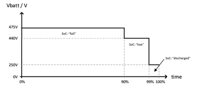
The battery voltage depends on the state of charge, and the battery voltage model is shown in Figure 7. This model already includes the above-mentioned overshoot and transient voltage under abnormal conditions.

Figure 7: Battery voltage model
Assuming that the battery operates at full voltage 90% of the time:
Vstress2=475V; 9% of the time, Vlowsoc=440V; for the remaining 1% of the time, assuming the battery is discharged, Vdischg=250V.
Applying conditional models
After defining the electrical stress conditions of the OBC, the application parameters such as duty cycle and switching frequency need to be defined and are described in Table V.
The PFC operates in continuous conduction mode (CCM). The assumed switching frequency of the PFC is 100 kHz. The duty cycle varies from 3% to 97% within the AC input half cycle.
For the DC-DC stage in the OBC, a full-bridge topology is assumed at a maximum frequency of 500 kHz and a duty cycle of 50%. For the HV-LV DC-DC module, a full-bridge topology is assumed with a maximum switching frequency of 500 kHz and a duty cycle of 50%, the same as the DC-DC stage in the OBC.

IV. Examples of cosmic radiation assessment results
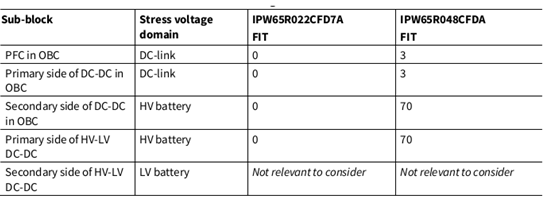
This section shows the cosmic radiation assessment results based on the previous mission profile and other models. Take the two generations of automotive-grade CoolMOS, IPW65R048CFDA and IPW65R022CFD7A, as examples:

Figure 8: Single device failure rate
The results from the perspective of a single device show that the CFD7A series has stronger cosmic radiation robustness than the older generation CoolMOS. This feature is even more important if the battery voltage is 475V. The older generation CFDA series is suitable for a battery voltage of 420V. If the FIT rate is viewed from a system perspective, it is only necessary to multiply the FIT value by the number of devices used in the PFC and DCDC stages. In the Totem pole PFC slow tube and the DCDC stage in the OBC, the CFD7A solution is used as an example. From the perspective of the total FIT rate, no further reliability analysis is required.

Figure 9: System-level failure rate
V. Conclusion
As the penetration rate of new energy vehicles increases, especially in China, it has reached about 24%. The reliability of on-board OBC/DCDC has become increasingly important. Performance is easy to show in the laboratory stage, but the reliability of a large number of products over several years is not easy to perceive but is very important. In OBC/DCDC applications, as the voltage level increases, cosmic radiation is not mentioned much, but its importance cannot be ignored.
This article explains the failure mechanism and the FIT rate evaluation method at the system level for the specific application of OBC/DCDC. The mission profile model of the actual application may be slightly different from the general model in this article. Infineon will make specific evaluations for different mission profile models to ensure system-level reliability.
References
1.Infineon-MOSFET_CoolMOS_CFD7A_Cosmic_Radiation_Assessment-ApplicationNotes-v01_00-EN
2.Infineon-MOSFET_CoolMOS_CFD7A_650V-ApplicationNotes-v02_00-EN
3.Infineon-Reliability_of_SiC_power_semiconductors-Whitepaper-v01_02-EN
4.SystemPlus_GaN_on_Si_HEMT_vs_SJ_MOSFET_Technology_and_Cost_comparison
5.Infineon-Physics of Cosmic Radiation-induced Failures in High Voltage Power Devices
Previous article:EMC filter design with REDEXPERT
Next article:WPG Group launches 100W PD power adapter solution based on Onsemi products
- MathWorks and NXP Collaborate to Launch Model-Based Design Toolbox for Battery Management Systems
- STMicroelectronics' advanced galvanically isolated gate driver STGAP3S provides flexible protection for IGBTs and SiC MOSFETs
- New diaphragm-free solid-state lithium battery technology is launched: the distance between the positive and negative electrodes is less than 0.000001 meters
- [“Source” Observe the Autumn Series] Application and testing of the next generation of semiconductor gallium oxide device photodetectors
- 采用自主设计封装,绝缘电阻显著提高!ROHM开发出更高电压xEV系统的SiC肖特基势垒二极管
- Will GaN replace SiC? PI's disruptive 1700V InnoMux2 is here to demonstrate
- From Isolation to the Third and a Half Generation: Understanding Naxinwei's Gate Driver IC in One Article
- The appeal of 48 V technology: importance, benefits and key factors in system-level applications
- Important breakthrough in recycling of used lithium-ion batteries
- Innolux's intelligent steer-by-wire solution makes cars smarter and safer
- 8051 MCU - Parity Check
- How to efficiently balance the sensitivity of tactile sensing interfaces
- What should I do if the servo motor shakes? What causes the servo motor to shake quickly?
- 【Brushless Motor】Analysis of three-phase BLDC motor and sharing of two popular development boards
- Midea Industrial Technology's subsidiaries Clou Electronics and Hekang New Energy jointly appeared at the Munich Battery Energy Storage Exhibition and Solar Energy Exhibition
- Guoxin Sichen | Application of ferroelectric memory PB85RS2MC in power battery management, with a capacity of 2M
- Analysis of common faults of frequency converter
- In a head-on competition with Qualcomm, what kind of cockpit products has Intel come up with?
- Dalian Rongke's all-vanadium liquid flow battery energy storage equipment industrialization project has entered the sprint stage before production
- Allegro MicroSystems Introduces Advanced Magnetic and Inductive Position Sensing Solutions at Electronica 2024
- Car key in the left hand, liveness detection radar in the right hand, UWB is imperative for cars!
- After a decade of rapid development, domestic CIS has entered the market
- Aegis Dagger Battery + Thor EM-i Super Hybrid, Geely New Energy has thrown out two "king bombs"
- A brief discussion on functional safety - fault, error, and failure
- In the smart car 2.0 cycle, these core industry chains are facing major opportunities!
- The United States and Japan are developing new batteries. CATL faces challenges? How should China's new energy battery industry respond?
- Murata launches high-precision 6-axis inertial sensor for automobiles
- Ford patents pre-charge alarm to help save costs and respond to emergencies
- New real-time microcontroller system from Texas Instruments enables smarter processing in automotive and industrial applications
- Huada EVHC32F460 development board evaluation summary
- Four major predictions for the consumer MEMS market in 2021
- FPGA Implementation of Light Band Centerline Extraction in 3D Scanning Images
- Help, looking for a schematic diagram of asm1142
- RT-Thread system solves the problem that low-priority tasks cannot be suspended with high-priority tasks
- Automatically load Cadence Toolbox functional components
- Let's read together! ——Power supply design book recommendations
- What is the problem with the progress bar when AD is doing PCB routing? (The problem has been solved, welcome to continue discussing)
- EEWORLD University Hall----Live Replay: Introduction to Jacinto?7 Industrial Application Processor
- [Repost] How to quickly distinguish common SMT patch components


 Building real-time machine learning systems
 Vehicle-mounted DCDC power supply EMC test specification V1.0


 京公网安备 11010802033920号