Innovative technologies such as solar and wind power are replacing traditional fuel-based power plants at an accelerating rate and are already outpacing expensive “power plants” due to improvements in energy storage and collection methods, which offer significant cost savings.
With governments supporting renewable energy through policies and incentives, there are many opportunities for improvement and growth in public energy infrastructure and its associated grid structure.
latest progress
Older grid structures include one-way power delivery and limited energy generation, such as fossil fuels, hydroelectric and nuclear power plants. Recent advances in renewable energy generation and collection are allowing the same grid to scale its generation resources (wind and solar) while creating flexible bidirectional distribution to meet different needs and storage options.
Specifically, for solar energy, inverters are usually required, which convert the DC voltage generated by photovoltaic (PV) modules into AC voltage before passing it back to the grid. One of the most common methods is through a string inverter scheme, where the DC voltage from the solar panel is fed into a DC/DC step-up and then into a DC/AC inverter before being connected to the grid.
Figure 1 shows a typical solar string inverter block diagram, which includes gate drive, current sensing, and processing. Power delivery for this configuration is usually accomplished using IGBTs, high voltage FETs, and more commonly, power integrated modules (PIMs) containing integrated IGBTs and diodes.
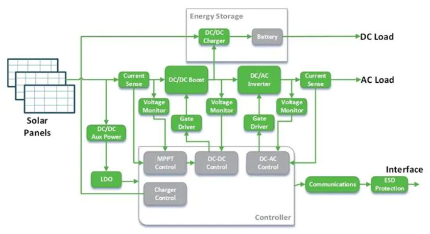
Figure 1: Solar string inverter block diagram
Electric vehicle charging is another industry with similarly high power demands. Electric vehicles are becoming more popular at an unprecedented rate. Unfortunately, their charging stations have lagged behind. The infrastructure for charging electric vehicles has not yet reached the same availability as gas stations, and charging times are much longer than refueling. A DC fast charging system operating at a power level of 350 kW can fully charge a vehicle in less than 10 minutes.
Figure 2 shows an example of a typical DC fast charging block diagram with the power path components and associated processing and peripherals.
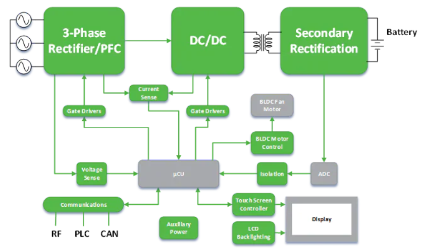
Figure 2: DC fast charging block diagram of an EV charging station
Silicon carbide (SiC)-based components have proven to offer better power transmission solutions for public energy infrastructure, such as power grids and EV charging stations. Such solutions, in turn, can provide improvements in terms of better conduction losses, leakage current, thermal management, surge capacity, and power density. Additionally, SiC-based technologies can increase overall efficiency, as well as improve reliability and reduce overall footprint. Industry-leading companies such as ON Semiconductor offer a range of SiC devices, so let’s explore these devices and delve deeper into some of their applications.
Why SiC technology is a better solution
Whether it’s solar, EV charging, or server applications, it’s been shown that SiC technology can outperform traditional silicon devices and modules, such as silicon IGBTs/MOSFETs. But let’s start with a topic that jumps to every designer’s mind: efficiency.
How does SiC improve efficiency? Many factors are involved, but primarily, SiC's advantages include higher operating temperature and frequency (up to 1 MHz) at lower conduction losses (Vf), as well as higher voltage and current ratings (up to 1800 V and 100 A), which in turn provide higher power efficiency and less heat dissipation than silicon MOSFETs.
See Figure 3 for how SiC technology delivers some of the highest overall power capabilities for high voltage and high current applications.
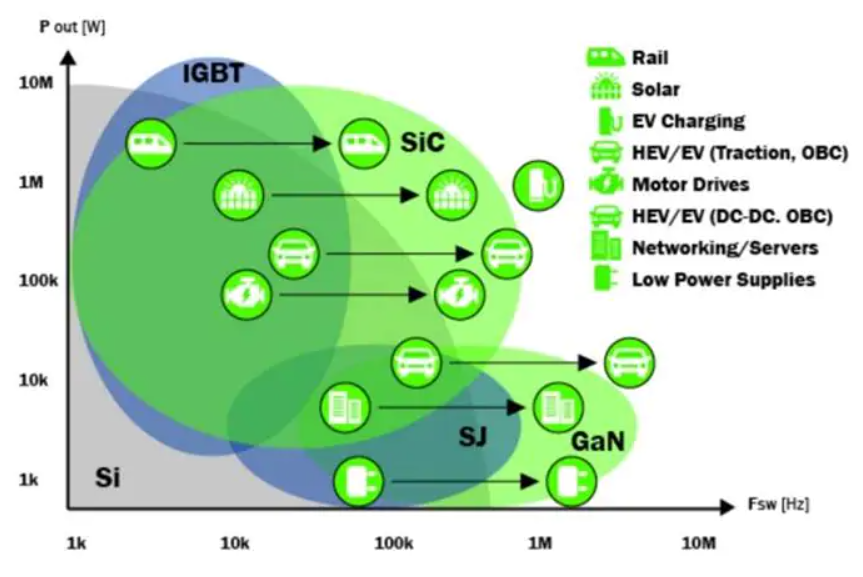
Figure 3: Relationship between power capability and switching frequency of high-power transistors
Given the lower on-resistance and higher power capabilities of these SiC devices, SiC-based solutions translate into higher operating efficiency.
Figure 4 shows a SiC-based diode and MOSFET in series, which reduces conduction losses by up to 73% in a typical 5kW boost converter application.
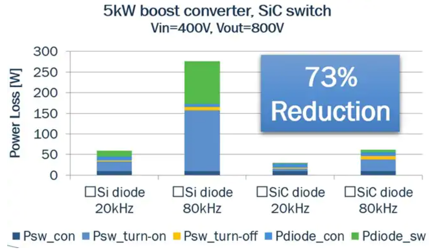
Figure 4: Example of using SiC components to achieve higher power efficiency in a 5kW boost converter
The footprint of a SiC-based circuit is typically much smaller due to lower size requirements for the associated inductors and capacitors. In fact, in some cases, it is 75% smaller due to higher switching frequencies. This allows for higher power density. Although SiC MOSFETs are typically 4 times more expensive than traditional silicon MOSFETs, the overall system cost goes down due to these smaller inductors and capacitors, while reducing the overall area.
In terms of product assembly and mechanical integration, ON Semconductor’s PIMs, such as the Q0/Q1/Q2PACK modules, where SiC devices are integrated to help reduce peripheral system development, have been proven to simplify the manufacturing process and reduce development risk while allowing for faster time to market.
In addition, discrete, non-integrated solutions usually require more time to design and install thermal systems, such as isolation pads and heat sinks, while also bringing the risk of poor thermal contact. PIM solutions can simplify the assembly process, thereby reducing time/cost and improving reliability, while also making the final product more compact due to the advantages in power density.
Figure 5 shows a comparison between the discrete solution and the PIM module assembly process.
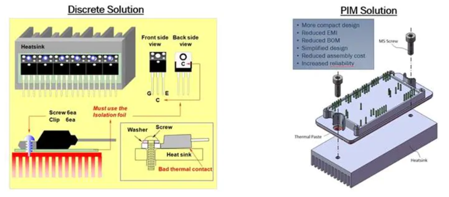
Figure 5: Assembly comparison between discrete solution and ON Semiconductor PIM solution
SiC Power Solutions from ON Semiconductor
ON Semiconductor's PIM modules provide faster switching speeds, higher power efficiency and higher power density. These solutions can also reduce system cost and size, but that's not all. PIM modules are not always preferred over discrete components, mainly based on the power rating of the application and performance and cost considerations. Therefore, ON Semiconductor provides both discrete and PIM SiC solutions.
Figure 6 shows how to choose between a discrete solution or a PIM solution.
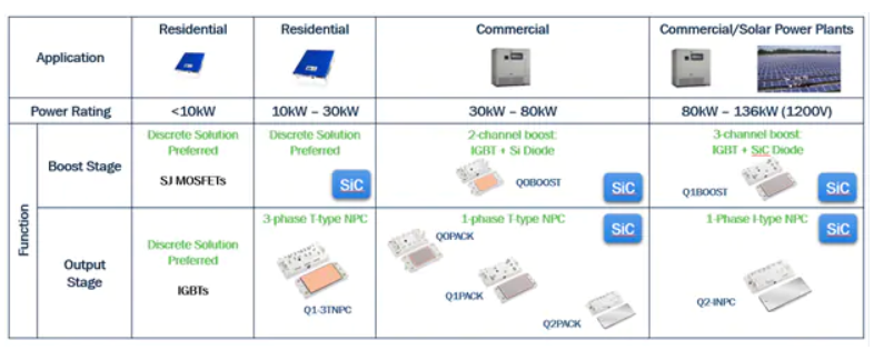
Figure 6: When to use a discrete or modular solution
High voltage auxiliary supplies for applications such as UPS, motor drives or PV inverters typically have a DC bus voltage of 300 VDC to 1000 VDC, which makes it difficult to integrate low voltage auxiliary supplies for displays, fans or heaters. But SiC MOSFETs have a higher blocking voltage and a wider input voltage range, allowing greater system flexibility and functionality. In addition, as mentioned in the SiC Advantages section, higher frequencies and lower on-resistances result in smaller, higher power density solutions. However, let's look at a direct comparison between an ESBC configuration power supply running at 75 kHz and a SiC power supply running at 300 kHz. The SiC power supply is smaller in size (by about half), has 20% more power output, and is significantly more efficient.
See Figure 7 for a comparison of size and efficiency.
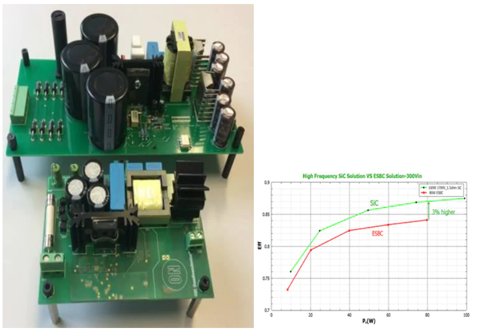
Figure 7: Comparison of high voltage SiC and ESBC
ON Semiconductor offers a variety of switch technologies and package types, as well as isolated drivers, depending on the application.
See Figure 8 for ON Semiconductor’s complete SiC device portfolio.
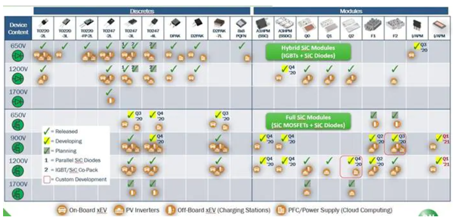
Figure 8: ON Semiconductor SiC product portfolio
Previous article:IGaN and A-PRO jointly develop 8-inch 650V GaN device
Next article:Vicor Appoints David Krakauer as Vice President of Corporate Marketing and Channel Strategy
Recommended ReadingLatest update time:2024-11-16 14:32


- Popular Resources
- Popular amplifiers
-
 Optimization design of SGT_MOSFET peak oscillation in synchronous rectification circuit
 -
 Study on the Behavioral Model of Silicon Carbide MOSFET Power Module and EMI Prediction of Low-Voltage Auxiliary Power Supply
 -
 Theory and practice of small-size MOS device models for VLSI simulation
 -
 Power Electronics Technology 2nd Edition (Li Jie, Chao Xiaojie, Jia Weijuan, Yang Jiayi, Lai Wei)
- MathWorks and NXP Collaborate to Launch Model-Based Design Toolbox for Battery Management Systems
- STMicroelectronics' advanced galvanically isolated gate driver STGAP3S provides flexible protection for IGBTs and SiC MOSFETs
- New diaphragm-free solid-state lithium battery technology is launched: the distance between the positive and negative electrodes is less than 0.000001 meters
- [“Source” Observe the Autumn Series] Application and testing of the next generation of semiconductor gallium oxide device photodetectors
- 采用自主设计封装,绝缘电阻显著提高!ROHM开发出更高电压xEV系统的SiC肖特基势垒二极管
- Will GaN replace SiC? PI's disruptive 1700V InnoMux2 is here to demonstrate
- From Isolation to the Third and a Half Generation: Understanding Naxinwei's Gate Driver IC in One Article
- The appeal of 48 V technology: importance, benefits and key factors in system-level applications
- Important breakthrough in recycling of used lithium-ion batteries
- Innolux's intelligent steer-by-wire solution makes cars smarter and safer
- 8051 MCU - Parity Check
- How to efficiently balance the sensitivity of tactile sensing interfaces
- What should I do if the servo motor shakes? What causes the servo motor to shake quickly?
- 【Brushless Motor】Analysis of three-phase BLDC motor and sharing of two popular development boards
- Midea Industrial Technology's subsidiaries Clou Electronics and Hekang New Energy jointly appeared at the Munich Battery Energy Storage Exhibition and Solar Energy Exhibition
- Guoxin Sichen | Application of ferroelectric memory PB85RS2MC in power battery management, with a capacity of 2M
- Analysis of common faults of frequency converter
- In a head-on competition with Qualcomm, what kind of cockpit products has Intel come up with?
- Dalian Rongke's all-vanadium liquid flow battery energy storage equipment industrialization project has entered the sprint stage before production
- Allegro MicroSystems Introduces Advanced Magnetic and Inductive Position Sensing Solutions at Electronica 2024
- Car key in the left hand, liveness detection radar in the right hand, UWB is imperative for cars!
- After a decade of rapid development, domestic CIS has entered the market
- Aegis Dagger Battery + Thor EM-i Super Hybrid, Geely New Energy has thrown out two "king bombs"
- A brief discussion on functional safety - fault, error, and failure
- In the smart car 2.0 cycle, these core industry chains are facing major opportunities!
- The United States and Japan are developing new batteries. CATL faces challenges? How should China's new energy battery industry respond?
- Murata launches high-precision 6-axis inertial sensor for automobiles
- Ford patents pre-charge alarm to help save costs and respond to emergencies
- New real-time microcontroller system from Texas Instruments enables smarter processing in automotive and industrial applications
- Discover Schottky diodes in daily life
- TCP protocol requires restarting the circuit board for each connection
- EETALK: What products might be reshaped in the 5G era? (Give away 10-100 Chip Coins)
- How to layout the PCB of photovoltaic power supply?
- Questions and Answers about bq24650 and BQ25601
- Ultrasonic utility knife (cutting knife) 2999RMB ???
- High salary recruitment of visual software engineers
- Circuit short circuit protection burns out DC-DC, output 12V changes drastically to around 28V, green is the flip protection signal
- EEWORLD University ---- Matlab Machine Learning
- How to write arm-poky mixed Makefile

 Optimization design of SGT_MOSFET peak oscillation in synchronous rectification circuit


 京公网安备 11010802033920号